Assembly and Operating Instructions
– Industrial sectional door MakroPro 100
,
MakroPro Alu 100
6
EN
IIiO/BS/MakroPro100/10/2015/ID-92974
+
Technical description
[D000383]
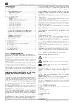
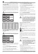
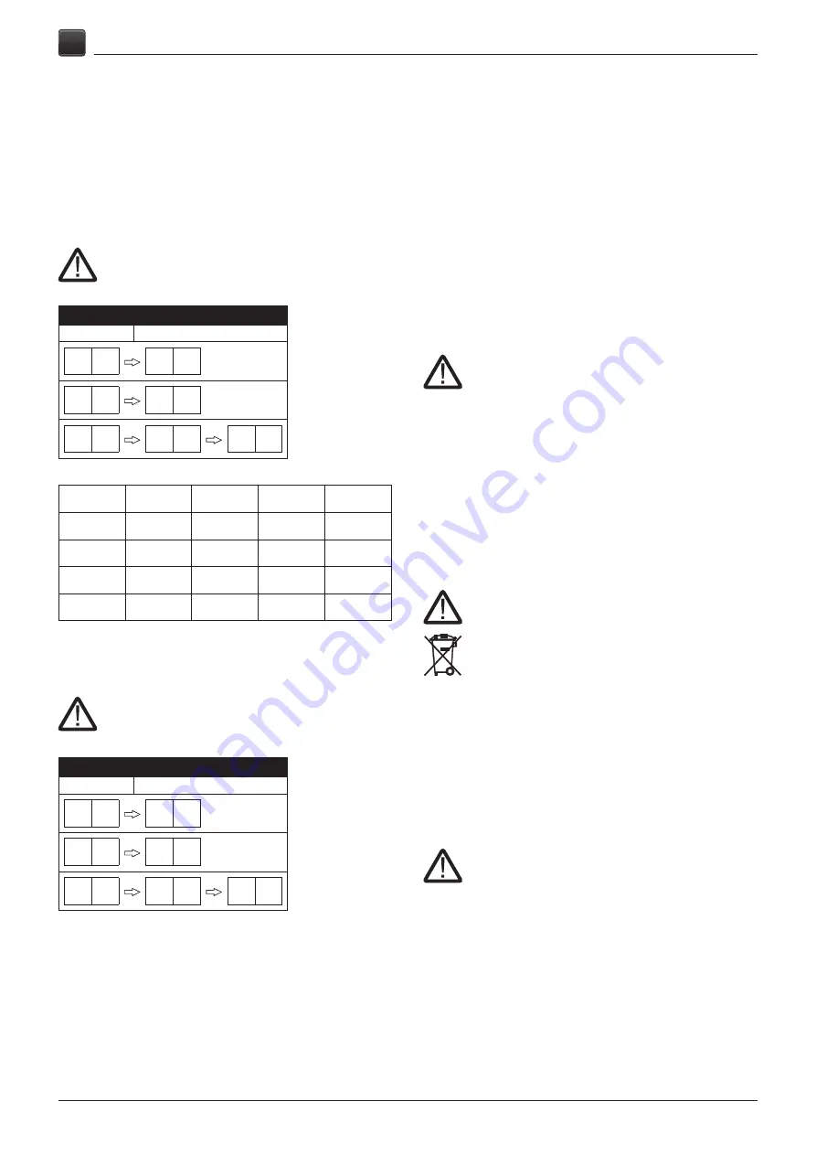
7.11. CIRCUIT DIAGRAM FOR LEADING PHOTOCELLS
(TWO CHANNEL SYSTEM)
Circuit diagram for control units TS-970, TS-970AW and TS-981 is shown on
fig. 160. LED indicators provide information on proper photocells connection.
Indicator CH1 provides information on the work of the photocells protecting
the door exterior closing edge, and indicator CH2 - the door interior closing
edge. When the leading photocells are connected and indicator OUT lights
redly, replace the plugs R1 and T1. When the door is closed, indicator OUT
lights redly. After the proper connection of the photocells, program the door
controller and adjust properly the limit switch for the door upper position.
Circuit diagram to connect photocells and open wicket door sensor is shown
on fig. 160.1.
Wrong adjustment of the limit switch for the door upper
position results in the damage of the leading photocells.
[D000384]
Controller programming
Function
Set-up
0. 1
. 3
2. 1
. 2
1. 5
—. 0
—. 9
[D000385]
Status
indication
LED OUT
LED CH1
LED CH2
Controller
message
Proper
connection
green colour
yellow colour
yellow colour
none
Connection
error
red colour
———
———
F.2.9
Interior photocell
failure
red colour
yellow colour
———
F.2.9
Exterior photo-
cell failure
red colour
———
yellow colour
F.2.9
[D000386]
7.12. CIRCUIT DIAGRAM FOR LEADING PHOTOCELLS
(ONE CHANNEL SYSTEM)
Circuit diagram for control units TS-970, TS-970AW, TS-981 is shown on fig.
155 and 155.1.
Wrong adjustment of the limit switch for the door upper
position results in the damage of the leading photocells.
[D000384]
Controller programming
Function
Set-up
0. 1
. 3
2. 1
. 2
1. 5
—. 0
—. 9
[D000444]
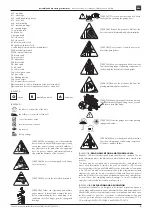
7.13. INSTALLATION OF BUMPER PLATE FOR LEADING
PHOTOCELLS
Installation is shown on fig. 170. The plate should be installed when the door
is equipped with leading photocells.
[D000454]
7.14. CIRCUIT DIAGRAM FOR WARNING LIGHT
Circuit diagram to connect warning light to control panel TS-970AW, TS-981 is
shown on fig. 180.
[C000328]
7.15. INSTALLATION OF SPIRAL CABLE HOLDER
Installation of an additional spiral cable holder for TS-961, TS-970, TS-
970AW, TS-981 control panel is shown on fig.190.
[B000169]
7.16. INSTALLING THE PADLOCK HOLDER
The installation of the padlock holder on the door leaf/shell is shown in fig. 195.
[B000014]
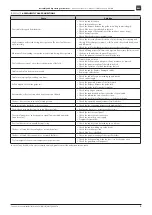
7.17. FAULTS DURING DOOR INSTALLATION
There is a risk that some faults may occur during door installation, which could
be easily avoided, provided that:
• vertical guide rails are installed properly acc. to the present Instruction,
• the door leaf in its closed position is flat, segments have no deformations. If
any irregularities are observed, adjust the hinges,
• side hinges are adjusted as stated in the Instruction,
• bumpers were pressed when the door is in its open position (fig. 26),
• all joinings are bolted properly.
Non-observation of the above basic recommendations may lead to troubles in
door operation, door damage or, as a result, provide to the loss of the warranty.
[A000007]
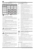
8. ADDITIONAL REQUIREMENTS
After the installation is completed, it must be checked that the door is fitted with
CE data plate according to the standard. If this plate is missing, fit the door with
such a data plate. After verifying the correct operation of the door, the Assembly
and Operating Instruction and door report book, if required, should be handed
over to the Owner.
• [B000013]
When the door is installed, the protective
foil should be immediately removed from the door
leaf. Failure to do so will result in a strong adherence
of the foil to the door sheet metal under the influence
of sun rays. This will make it impossible to remove the
foil and may lead to paint coating deterioration.
• Doors with electric drive must be opened according to
Assembly and Operating Instruction of the drive.
[A000008]
9. ENVIRONMENTAL PROTECTION
Packaging
Elements of packaging (cardboard, plastics, etc.) are classified as waste suitable
for recycling. Follow local legislation for specific material before throwing it away.
Scrapping
The product consists of many different materials. Most of the materials used are
suitable for recycling. Sort it before disposal, and then deliver to refuse collec-
tion and disposal area for recycling.
Follow local legislation for specific material before
scrapping.
[A000009]
Remember! Recycling of packaging materials
saves natural resources and reduces the amount of
wastes.
[A000016] The product is marked with „crossed-out wheelie bin” sign accord-
ing to European directive 2002/96/WE on waste electric and electronic equip-
ment. When the product is warned out or no longer in use, it should not be
dumped with normal household goods. The product user is obliged to dispose
it to the authorized disposal facilities for electric and electronic devices, like
local places to collect wastes, stores and other places recommended by the
manufacturer.
[C000034]
10. DOOR DISASSEMBLY
To disassemble the door, perform assembly procedure in a reverse order. Prior
to disassembly, disconnect power supply of the drive, close and lock the door.
• To remove the key connecting the shaft and actuator
as well as to disassemble the actuator is only allowed
when the door is its ultimate closed position.
• [A000060]
Disconnect the drive power supply during
all maintenance and inspection works.
• [C000233]
It is allowed to loosen the leaf supporting
cables only when the door is in its closed position.
[B000015]
11. OPERATING REMARKS
The basic conditions for the proper door usage that guarantee its durable and
trouble-free operation:
• provide free water drain in the area of bottom sealing,
• protect the door against harmful agents (including corrosive agents, like ac-
ids, alkali, salts), which may damage the paint coating and metal.
• protect the door against plaster, paints and solvents which may cause stains,
during finishing or repairing works,
• electrically operated doors must be opened according to the Instruction pro-
vided with the electric equipment,
• check the proper regulation of hinges if the excessive resistance during door


