15
3.5.5
The battery capacity indicator is provided to give an approximation of battery capacity
remaining. Each bar on the LCD approximates to a ¼ of the capacity. However, this indicator
relies on sensing battery voltage that will rise and fall depending on the amount of power
being demanded at any given time, ambient temperatures etc, hence the meter should only
be used for indication purposes.
3.5.6
The battery capacity indicator, built into the top of the battery (four LEDs) provides a similar
indication and operates on the same principle.
3.5.7
Under heavy power situations (full throttle or high levels of assist) the battery voltage will
temporarily dip resulting in the capacity meter showing a lower level of charge. When the
heavy power usage is reduced, the capacity meter will rise again as the battery naturally
recovers its voltage.
3.5.8
During the discharge period of the battery, the voltage will drop from an initial voltage of
nearly 42 Volts to a minimum of 31.5 Volts. The bulk of the discharge period will be in the
range of 38 to 36 Volts which provides the optimum performance for the bicycle. Hence due
to this wide range in voltage, the performance of the bike will vary depending on the state of
charge of the battery. To achieve the best possible performance, it is better to start a
journey with a fully charged battery and to recharge it at the end of each journey.
3.6
Brakes
3.6.1
Disc brakes are fitted to the front and V brakes to the rear wheels of the bicycle.Disc brakes
offer several advantages over traditional rim brakes,including better braking in wet, muddy
or other adverse conditions and less braking power fade over extended downhill braking.
3.6.2
Details of how to adjust and maintain your brakes are as follows:
3.6.3
Regularly inspect the brake padsfor wear. If the front brake pads have reached the wear
limit of 1mm, replace them immediately. The rear brake blocks should be checked by a
bicycle mechanic and replaced when necessary.
3.6.4
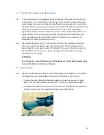
Front brake, remove the caliper from the fork leg, complete with the mount adapter by
removing the two 6mm Allen caliper fixing screws. The pads can then be removed by
unscrewing and removing the pad retaining screw (which passes through the tabs of the
brake pads) using a 3mm Allen wrench. Then lift the pads complete with the spring out of
the rotor slot in the caliper body.
Warning!
Do not loosen any other screws on the caliper.
3.6.5 To refit the pads, hold the pads complete with spring as an assemblyand insert into the
caliper slot with the metal backing towards the pistons.Refit the pad retaining screw
ensuring it passes through the holes in the pad tabs and through the hole in the spring and
tighten to 3– 5 N.m. Refit the caliper loosely using the two Allen screws, apply the brake


