background image

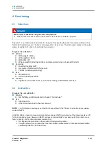
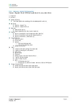
Product:  Eleganza 1 
Version:  01


25/68


8.8 

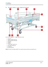
Eleganza 1 (1GTP) 

– Single collapsible side rails controlled from bottom 


1.  Foot end 

2.  Mattress platform consisting of fixed HPL parts 

3.  Single collapsible side rails controlled from the bottom 

4.  Head end 

5.  Protective bumper 

6.  Bed foot with the possibility of fixation to the floor 

7.  Lockable box for mains cable 

8.  Accessory rail 

9.  Side rail release mechanism 

10.  CPR lever 

11.  Linen shelf with non-removable supervisor panel 

12.  Segufix holders 


NOTE  For safe, easy handling, LINET

® 

recommends having two technicians assemble the bed.


Fig. 11 Eleganza 1 (1GTP) 

– Single collapsible side rails controlled from bottom


Summary of Contents for Eleganza 1

Page 1: ...User manual and technical description D9U001GT0 0201 Version 01 Print date 2017 06 Eleganza 1 Hospital bed for standard care...

Page 2: ...bosserhoff GmbH Hauptstra e 4 6 58739 Wickede Ruhr Germany D9U001GT0 0201 Version 01 Print date 2017 06 Copyright LINET s r o 2017 Translation LINET 2017 All rights reserved All trademarks and brands...

Page 3: ...ery Activation 17 7 1Placement of Control Section 17 7 2Removing the Isolating Foil 17 7 3Isolating Foil 17 8 Assembly 18 8 1Potential Equalisation 18 8 2Lockable box for mains cable psychiatric versi...

Page 4: ...r Cleaning and Disinfection of the Bed 50 12 2 General Instructions for Cleaning and Disinfection 52 12 3 Choosing of Detergents or Disinfections 53 13 Troubleshooting 54 13 1 Sound signals of the bed...

Page 5: ...arning risk of physical injury Danger risk of fatal injury 1 1 2 Structure of Warning Notices 1 2 Other symbols 1 2 1 Instructions Structure of instructions Perform this step Result if necessary 1 2 2...

Page 6: ...al current Type B instruments Safety isolating transformer general CE mark of conformity with EU regulation Safety mark bed certified in T V S D Jack for attachment of conductor for potential equalisa...

Page 7: ...Product Eleganza 1 Version 01 7 68 1 4 Serial label with UDI...

Page 8: ...ed by the manufacturer Do not apply excess weight or loads to the bed according to SWL Safe Working Load During peak loads or unavoidable excess loads CPR place the mattress platform in the lowest pos...

Page 9: ...ly modified with the manufacturer s approval Ensure there is no danger of crushing or otherwise injuring the patient s limbs e g between side rails and mattress platform between movable parts etc befo...

Page 10: ...40 C The relative humidity is between 30 and 75 The atmospheric pressure is between 795 hPa and 1060 hPa The bed may not be used and stored in indoor environments Where there is a risk of explosion C...

Page 11: ...directives EN 60601 1 2006 A1 2013 EN 60601 1 2 2007 EN 60601 1 6 2010 EN 60601 2 52 2010 EN ISO 10993 5 2009 EN ISO 10993 10 2013 93 42 EEC 2011 65 EU The manufacturer adheres to a certified quality...

Page 12: ...2010 4 2 Incorrect Use Eleganza 1 is not suitable for Patients Not fulfilling conditions stated in chapter Correct use Use Intensive care Other than described in the user manual NOTE For information...

Page 13: ...o Side rails Without side rails s Single collapsible side rails powder coated o Split plastic side rails o Castors 125 mm Tente Motion with individual braking system s 125 mm Tente Motion with centra...

Page 14: ...0 mm Tente Motion with central braking sytem o 150 mm Tente Motion fifth castor o Control Elements supervisor panel foot controls handset with illuminated keyboard without illuminated keyboard satelli...

Page 15: ...Fixation material is not part of the delivery Control Elements Non removable ACP Nurse control panel supervisor panel fixed to the linen shelf s Plug Play connector for removable handset o Handset wi...

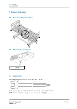
Page 16: ...ure the brakes are released while moving the bed 6 2 Setup Set up the bed as follows Unpack the bed Check the delivery see Scope of Delivery Remove isolating foil from mains control box see Battery Ac...

Page 17: ...Section 7 2 Removing the Isolating Foil 7 3 Isolating Foil Check if isolating foil is complete and undamaged as shown If isolating foil is damaged contact the manufacturer s service department immedi...

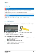
Page 18: ...the bed on which the patient in question is lying Use a standard hospital connector Fig 1 Make sure the connectors match Make sure there is no possibility of accidental disconnection Before moving the...

Page 19: ...Remove the lock by pulling WARNING Risk of damaging the box or mains cable due to incorrect use Never leave the doors on the box opened There is a risk of damaging by usage or by a mentally unstable p...

Page 20: ...ull out mattress platform parts Install mattress platform parts in directions indicated on label Fig 6 The correct fitting of section is signalized by hearable click Ensure that mattress platform sect...

Page 21: ...apsible side rails 3 Side rail release mechanism 4 Head end 5 Handset 6 Castors 7 Central castor system lever 8 Removable plastic parts 9 Linen shelf 10 Supervisor board NOTE For safe easy handling LI...

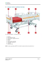
Page 22: ...ible side rails 3 Control element integrated in side rail 4 Head end 5 Castors 6 Side rail release mechanism 7 Central castor system lever 8 Linen shelf 9 Supervisor board NOTE For safe easy handling...

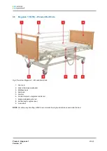
Page 23: ...lease mechanism 3 Mattress base 4 Head end 5 Castors 6 Control element integrated in side rail 7 Single collapsible side rail 8 Central castor system lever 9 Linen shelf NOTE For safe easy handling LI...

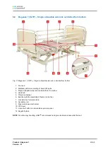
Page 24: ...latform consisting of fixed HPL parts 5 Head end 6 Handset 7 Protective bumper 8 Castor 150 mm 9 Lockable box for mains cable 10 Accessory rail 11 CPR lever 12 Central castor system lever 13 Linen she...

Page 25: ...he bottom 4 Head end 5 Protective bumper 6 Bed foot with the possibility of fixation to the floor 7 Lockable box for mains cable 8 Accessory rail 9 Side rail release mechanism 10 CPR lever 11 Linen sh...

Page 26: ...of injury due to incorrectly installed bed ends Ensure bed ends are correctly inserted especially when moving the bed Ensure bed ends locks are locked especially when moving the bed WARNING Risk of i...

Page 27: ...ner posts Slide bed end into slots on corners posts with coloured panels outside Lock safety levers on corner posts Remove bed ends as follows Unlock safety levers on corner posts Pull bed end upward...

Page 28: ...des a 6 month warranty for the full function of batteries Check the battery functionality at least once a month in accordance with the user and service manuals and have the battery changed if necessar...

Page 29: ...y is sufficient charging completed Short flashing short intermittent illumination circa 1 8 sec Battery is charging continue charging until the LED is extinguished In emergency cases the battery can b...

Page 30: ...ition This status will be cancelled automatically when the bed switches to sleep mode 9 5 Removing the Bed from Service How to remove the bed from service Disconnect the bed from the mains Disconnect...

Page 31: ...ng individual functions on the supervisor control panel affects all of the control elements If the bed does not react to individual position settings Check whether the function is disabled on the supe...

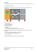
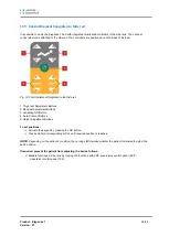
Page 32: ...al STOP Button 3 Activating GO Button 4 Thigh rest Lock Button 5 Thigh rest Lock LED 6 Backrest Lock Button 7 Backrest Lock LED 8 Height Lock Button 9 Height Lock LED 10 Reverse Trendelenburg Button 1...

Page 33: ...Auto Contour Buttons simultaneous setting of back and thigh rest 7 Foot Control Lock LED 8 Foot Control Lock Button 9 Trendelenburg Button mattress platform tilt only 10 Reverse Trendelenburg Button...

Page 34: ...on the bed except the locked functions Pressing a function button will keep the keypad active for another 3 minutes It is necessary to activate the keypad again if the 3 minute period without pressing...

Page 35: ...rest the backrest will move into an upright position 62 Trendelenburg position 12 The Trendelenburg position serves as an anti shock position All parts of the mattress platform are flattened Mattress...

Page 36: ...Height Adjustment Button 7 Height Lock LED 8 Flashlight Button 9 Flashlight To switch on the flashlight Press and hold flashlight button 8 and flashlight 9 on the top of the handset will light up Set...

Page 37: ...o set positions Activate the keypad by pressing the GO button Press and hold corresponding button until required position is reached NOTE Depending on the patient s condition the nursing staff decides...

Page 38: ...ng GO Button 4 Auto Contour Buttons 5 Height Adjustment Buttons To set positions Activate the keypad by pressing the GO button Press and hold corresponding button until required position is reached NO...

Page 39: ...ivation 4 Foot Switch Raise Mattress Platform Set the position as follows Press foot switch for activation mini GO function Press and hold foot switch until desired position is reached WARNING Risk of...

Page 40: ...Press the backrest down using Mattress guard handle Upper part of the side rails in case the split side rails are in upper position WARNING Risk of injury due to lowering the backrest too quickly Ens...

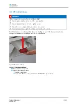
Page 41: ...ils cannot be dismounted The hospital personnel is responsible that side rails are locked in the highest position when the patient is on the bed To fold side rails down Pull out the lever 1 Fold side...

Page 42: ...ted by an audible click when locked in place Ensure that the side rail is locked properly 10 9 4 Full length side rails The full length side rails are components of the bed The side rails cannot be di...

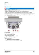
Page 43: ...are unlocked 3 Braked All of the castors are locked 10 10 2 Individual braking control Castor control with individual braking system Brake all castors of the bed by pressing the lever 1 by your foot c...

Page 44: ...aped top part with lock against unwanted rotation 4 metal hooks chrome plated lock against unwanted rotation 4 metal hooks stainless steel S shaped top part lock against unwanted rotation Infusion bot...

Page 45: ...pin locks are in place A plastic grab handle with an adjustable strap is attached to the lifting pole NOTE The date of manufacture is marked on the grab handle NOTE LINET recommends replacing the plas...

Page 46: ...e with movable parts of the bed This must be verified after installation of name holder 11 1 5 Urine bottle holder 11 1 6 Mattress Eleganza 1 bed is designed for the following mattress dimensions 200...

Page 47: ...Safety pin must be locked in place Dismount Eleganza Protector as follows Press and hold the releasing button 1 Push the protector up NOTE Protector cannot be used if the bed is equipped with plastic...

Page 48: ...ig 31 Side rails must be in upper position Square hole is pointed into the mattress platform Insert screws from the inside of the bed thru the securing holes in Extender Secure the screws with the pla...

Page 49: ...rail Fig 33 Side rails must be in upper position Square hole is pointed into the mattress platform Insert screws from the inside of the bed thru the securing holes in Extender Secure the screws with t...

Page 50: ...according to the degree of contamination of the bed and the cleaning mode daily before changing patient or complete Electronic parts that may be contaminated clean carefully and only their outer side...

Page 51: ...Product Eleganza 1 Version 01 51 68 After drying the bed place the mattress back on the mattress platform After drying the bed check functions of the bed...

Page 52: ...platform columns undercarriage covers and mattress 12 2 3 Complete Cleaning Cleaning before First Use It is recommended to clean the bed completely before the first use and then at least once in 4 8 w...

Page 53: ...tuators ABS ALU Part of mattress Efecta Material Daily C D Changing patient C D Complete C D Mattress core PU Cover P PU PA PES Material Shortcut Akrylonitrilbutadienstyren ABS Aluminium ALU Ethylene...

Page 54: ...t Faulty control element Notify the service department Lowering backrest from the upright position not possible Object under the backrest or in the drive mechanism Remove the object CPR handle is defe...

Page 55: ...uct label is located on the longitudinal rail of the mattress platform frame The product label contains information required for product queries and ordering replacement parts Information about spare...

Page 56: ...otors Check motor movement adjust bed positions Check for incorrect and interrupted movements Have defective motors replaced if necessary Check cables for signs of wear and entanglement Install new ca...

Page 57: ...ty check is stipulated in EN 62353 WARNING Incorrect safety checks can cause injuries Ensure that safety checks are performed by qualified or authorised personnel certified by the manufacturer Ensure...

Page 58: ...packaging materials are disposed of according to the symbols displayed and taken to an authorised disposal location The product consists of recyclable steel plastic and electronic components 15 2 Disp...

Page 59: ...tenance Do not continue to use the bed This product is covered by a 24 month warranty from the date of purchase The warranty covers all material and manufacturing related failures and errors Failures...

Page 60: ...Product Eleganza 1 Version 01 60 68 17 EC Declaration of Conformity...

Page 61: ...ess Platform Height Adjustment 125 mm castors 150 mm castors 37 cm 73 5 cm 39 5 cm 76 cm Maximum Back rest Angle 70 Maximum Thigh rest adjustment 34 Auto regression Ergoframe 10 6 cm Trendelenburg Rev...

Page 62: ...kg 45 kg 18 2 Electrical Specification Input Voltage 230 VAC 50 60 Hz Maximum Power Input Max 1 6 A 370 VA EN 60529 Safety Protection IP X4 Safety Class Class I with type B applied parts Electrical Mo...

Page 63: ...high frequency radiations are very low and unlikely to cause any interference to nearby electronic devices High frequency radiation CISPR 11 Class B Eleganza 1 is suitable for all institutions includ...

Page 64: ...cial or hospital environment Short time voltage drop short duration interruptions and slow voltage changes on the feeder input line IEC 61000 4 11 5 UT 95 short duration drop of UT within 0 5 cycles 4...

Page 65: ...n the vicinity of the instrument marked with the following symbol Radiated high frequency phenomena IEC 61000 4 3 3 V m 80 MHz to 2 5 GHz 3 V m a It is not possible to accurately indicate field intens...

Page 66: ...according to frequency of transmitter m Rated maximum output of transmitter W 150 kHz to 80 MHz 80 MHz to 800 MHz 800 MHz to 2 5 GHz 0 01 0 12 0 40 0 40 0 1 0 37 1 26 1 26 1 1 17 4 00 4 00 10 3 69 12...

Page 67: ...Log 19 1 Delivery Log Order number Customer Model number Serial number Delivery date Delivered by I hereby confirm personnel have been trained to correctly operate the bed Date Customer s Signature a...

Page 68: ...Product Eleganza 1 Version 01 68 68 19 2 Service and Maintenance Log Description of Service Date Performed By...

Reviews: