background image

Product: 

Latera


Version: 01 

33

/57 


Siderails 

9.10.1  Single collapsible siderail Latera Acute


The single collapsible siderails are components of the bed. The siderails cannot be dismounted. 


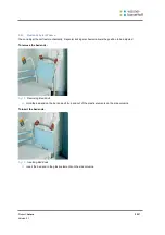
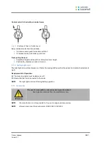
To collapse the siderails


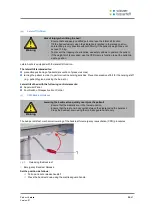
Fig 14


Collapsing the siderails


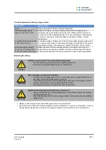
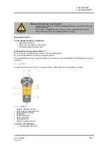
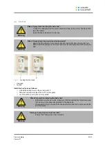
Risk of injury due to crushing!


Ensure that there are no objects or body parts between the tubes when folding the 
siderail up or down. 


Warning


Grip the siderail by the upper tube. 
Avoid the marked areas on the tube to prevent crushing. 


Release lock buttons. 


Fold down the side rail slowly toward the foot end. 


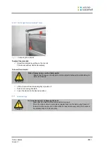
Folding up the siderails:


Grip the siderail by the upper tube. 
Avoid the marked areas on the tube to prevent crushing. 


Fold up the siderail slowly toward the head end. 


The locking mechanism latches. 

Summary of Contents for Latera

Page 1: ...User manual and technical description Latera Universal hospital bed D9U001L20 0201 Version 01 Print date 2017 06...

Page 2: ...l info wi bo de http www wi bo de D9U001L20 0201 Version 01 Print date 2017 06 Copyright LINET s r o 2017 Translation LINET 2017 All rights reserved All trademarks and brands are the property of the a...

Page 3: ...ation 18 Battery Operation 18 Removing the Bed from Service 20 Manipulation 21 Supervisor Panel 22 Handset 25 Foot Control Height Adjustment Examination Position 26 Foot Control Lateral Tilt 27 Satell...

Page 4: ...tera Version 01 4 57 TechnicalSpecifications 51 Mechanical Specifications 51 Electrical Specifications 51 EMC 52 PB 45 00 FEB Electronic System of Latera 52 Log 55 Delivery Log 55 Service and Maintena...

Page 5: ...warns against bodily injury Danger warns against potential mortal injury 1 1 2 Structure of Warning Notices Type and source of danger Measures to avoid the danger Signal words Other Symbols 1 2 1 Inst...

Page 6: ...ction against accidents due to electrical current Type B instruments Safety isolating transformer general CE mark Jack for attachment of conductor for potential equalisa tion Safe working load Warning...

Page 7: ...Product Latera Version 01 7 57 Serial label with UDI...

Page 8: ...bed with the correct mains supply only Ensure that the bed is operated by qualified personnel only Ensure that the patient health permitting has been informed about the operation of the bed and all ap...

Page 9: ...burg or Anti Trendelenburg position Always set mattress platform to its lowest position and single parts of mattress platform to horizontal position in case the patient is left on the bed without supe...

Page 10: ...the following standards EN 60601 1 EN 60601 1 2 EN 60601 1 4 EN 60601 1 6 EN 60601 2 52 EN ISO 10993 93 42 EEC 2011 65 EU The manufacturer adheres to a certified quality management system in complian...

Page 11: ......

Page 12: ...cerning uses other than those outlined in the Correct Use section above please contact wissner bosserhoff wissner bosserhoff s efforts in research design and manufacture make sure wissner bosserhoff p...

Page 13: ...lastic bed ends with coloured plastic inlay Acute Powder coated bed ends Acute Chromium plated bed ends Acute Bed ends design H05 with aluminium frame and removable laminated boards Thema Control Elem...

Page 14: ...ctivated Ensure that the brakes are released while moving the bed Setup Set up the bed as follows Unpack the bed Check the delivery see Scope of Delivery and Bed Variants Install equipment and accesso...

Page 15: ...formed by customer service or trained hospital per sonnel only Caution 1 2 3 4 1 1 11 10 9 8 7 6 5 Fig 1 Overview of Latera Acute 1 Foot Board 2 Single Collapsible Siderail 3 Emergency Backrest Releas...

Page 16: ...n folded up position 4 Foot Board 5 Linen Shelf with Supervisor Panel 6 Castor Control Lever 7 Foot Control for Height Adjustment and Examination Position 8 Foot Control for Lateral Tilt 9 150 mm Cast...

Page 17: ...n connector female Use equalisation connector if the patient is connected to any intravascular or intracardiac device Before connecting the patient to an intravascular intracardiac device Connect the...

Page 18: ...ndition only for a certain period of time which is dictated by the laws of physics and chemistry used in this type of Dry Lead Acid battery technology and their frequency and method of use The user is...

Page 19: ...battery fuses are faulty contact service department of the manufacturer in case of such signalisation Replacing the battery Damage to the bed due to incorrect battery replacement Have the battery repl...

Page 20: ...ions are the same as the operating conditions 8 3 1 Deactivating the Battery To avoid damaging the bed and the environment during storage Deactivate the battery on the supervisor panel To deactivate t...

Page 21: ...ve any items on the bed The bed is operated by different control elements Control elements depending on the model Supervisor Panel Handset Control Satellite optional Foot Control for Lateral Tilt opti...

Page 22: ...2 Activating GO Button 3 Thigh Rest Position Buttons 4 Thigh Rest Lock LED 5 Thigh Rest Lock Button 6 Backrest Position Buttons 7 Backrest Lock LED 8 Backrest Lock Button 9 Height Adjustment Buttons...

Page 23: ...ive for another three minutes 9 1 3 Function Buttons You can set different positions for example the height and tilt of the mattress platform adjust individual mattress platform elements etc with func...

Page 24: ...ion The cardiac chair position is for patients with cardiac arrhythmia and breathing difficulties Settings after pressing position button 20 The foot of the mattress platform is tilted to the lowest p...

Page 25: ...ettings after pressing position button 19 The backrest and thigh rest are moved to the horizontal position The mattress platform is moved to its highest position You can disable this function If indiv...

Page 26: ...dapter enables quick mounting and dismounting e g replacing a defective handset using the handset for another bed Foot Control Height Adjustment Examination Position The foot control is optional and a...

Page 27: ...to set up the lateral tilt of the bed with your feet 1 2 3 4 Fig 7 Foot Control Lateral Tilt 1 Foot Switch Lateral Tilt 2 GO Button 3 Protection Frame against Unwanted Activation 4 Foot Switch Lateral...

Page 28: ...rest Adjustment Button 4 Height adjustment buttons Set the position as follows Activate the keypad by pressing the GO button Press and hold the function button until the desired position is reached NO...

Page 29: ...ts prevention of pressure sores turning the patient in order to perform routine nursing activities Prevents excessive effort for the nursing staff e g patient hygiene making the bed etc Lateral tilt o...

Page 30: ...nism allows the position to be adjusted To raise the calf rest Pull on both calf rest handles until the desired position is reached To lower the calf rest Hold both handles and pull the calf rest to t...

Page 31: ...d especially when moving the bed 1 2 Fig 11 Locking the bed ends 1 Unlocked 2 Locked Install the bed ends as follows Unlock the safety lever on the corner posts 1 Slide the bed ends into the slots on...

Page 32: ...l locking mechanism allows the position to be adjusted To remove the bed ends Fig 12 Removing Bed Ends Hold the bed end on the bar and pull it up and out of the plastic elements on the side columns To...

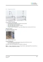
Page 33: ...ng Ensure that there are no objects or body parts between the tubes when folding the siderail up or down Warning Grip the siderail by the upper tube Avoid the marked areas on the tube to prevent crush...

Page 34: ...y parts or other objects between the rails before you lower the siderails Warning Lift the top rail of the siderail slightly in position 1 Push down locking handle 2 Lower the siderail to the desired...

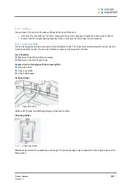
Page 35: ...es straight ahead upper lever position Castor control for bed with control levers 1 2 3 Fig 17 Positions of Castor Control Lever The control levers are located on both sides of the foot end Castor con...

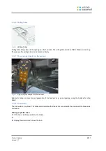
Page 36: ...ht Light The night light is an optional accessory It helps the nursing staff as well as the patient to orientate themselves at night Requirements for Operation The main room lights must be dimmed or o...

Page 37: ...pping over ensure that the lifting pole does not project out from the bed Lifting Pole Positions Over the backrest working position Parallel to the head board Fig 20 Safety pin locked in place To inst...

Page 38: ...astic hooks The hinge mechanism allows the rail to adjust to meet the patient s needs You can also fold the accessory rails away from the bed Load Capacity Maximum load of 5 kg without leverage Maximu...

Page 39: ...decubitus Mattress Compressor Fig 24 Holder for Anti decubitus Mattress Compressor The holder for the anti decubitus mattress compressor is only suitable for plastic bed ends Suspend the holder for th...

Page 40: ...Plug and play adapter for the handset Fig 27 Plug and play adapter for the handset Adapter for simple connection and separation of the handset e g when repairing using the handset for other beds 9 12...

Page 41: ...8 Only use detergents that are suitable for cleaning medical equipment Do not use abrasive powders steel wool or other material and cleaning agents that might damage the finish Never use any corrosive...

Page 42: ...alf rest handles CPR release handle Head and foot boards including aluminium columns and crossbars under the boards Siderails in highest position Freely accessible mattress surface Accessory rails 10...

Page 43: ...tic mattress platform covers Plastic undercarriage covers Telescopic columns Mattress on all sides Freely accessible metal parts on the mattress platform Cable ducts Lifting pole sleeve fitting Infusi...

Page 44: ...plug correctly Faulty power source Notify the service department Faulty control element Notify the service department Backrest cannot be lowered from the upright position There is an object under the...

Page 45: ...taching the maintenance plaque to the bed Ensure that the following maintenance work is performed every 12 months by the manufacturer or by a qualified service organisation trained and certified by th...

Page 46: ...the plug connectors are properly seated Motors Check motor movement adjust bed positions Check for incorrect and interrupted movements Have defective motors replaced if necessary Check cables for sig...

Page 47: ...in which the manufacturer declares that the ser vice organisation is qualified to perform maintenance on wissner bosserhoff products wissner bosserhoff makes every reasonable effort within research d...

Page 48: ...packaging material according to the symbols and by delivering it to an authorised person The product consists of recyclable steel plastic and electronic components Disposal 13 2 1 Within Europe To dis...

Page 49: ...ring maintenance Stop using the bed This product is covered by a 24 month warranty from the date of purchase The warranty covers all material and manufacturing related failures and errors Failures and...

Page 50: ...Product Latera Version 01 50 57 EC Declaration of Conformity...

Page 51: ...t for Lateral Tilt 135 kg Trendelenburg Anti Trendelenburg Tilt 16 16 Weight Depending on Equipment 160 kg Safe Working Load including Mattress and Accesso ries 200 kg Max Lifting Pole Load 75 kg Envi...

Page 52: ...ion Do not use electrical equipment near the bed Warning Latera is intended for the application in electromagnetic environment as specified below The customer or user of the bed is responsible for the...

Page 53: ...ns and slow voltage changes on the fee der input line IEC 61000 4 11 5 UT 95 short dura tion drop of UT within 0 5 cycles 40 UT 60 short dura tion drop of UT within 5 cycles 70 UT 30 short dura tion d...

Page 54: ...e in the vicinity of the instrument marked with the following symbol Radiated high fre quency phenomena IEC 61000 4 3 3 V m 80 MHz to 2 5 GHz 3 V m a It is not possible to accurately indicate field in...

Page 55: ...y Log Order Number Customer Model Number Serial Number Delivery Date Delivered By I hereby confirm that the personnel has been familiarised with the correct operation of the bed Date Customer s Signat...

Page 56: ...Product Latera Version 01 56 57 Service and Maintenance Log Description of Service Date Performed By...

Page 57: ...il from mains control box 1 by pulling strap 2 Check if isolating foil is complete and undamaged as shown in Fig 2 If isolating foil is damaged contact the manufacturer s service department immediatel...

Reviews: