background image

MCR41/MCR42 User Manual 


21


Troubleshooting 

Warning 

Warning description 

throubleshooting 

Low voltage level 

Low voltage level  

Replace battery or power supply 

TX of RX1 Battery Low  Low batteries level on TX1  

- change batteries  
- recharge the batteries 

TX of RX2 Battery Low  Low batteries level on TX2 

- change batteries  
- recharge the batteries 

Rear panel error 

The receiver doesn’t recognize the rear 
panel  

-Try to reconnect the rear panel 


Alarms 

Alarm description 

throubleshooting 

Device ID copy1 invalid 
Memory recovered 

Error during the initialization phase. The 
CRC-16 check of device data (copy 1) 
detects error. 

- no (the receiver 
automatically replace the 
corrupt copy1 with copy2) 

Device ID copy2 invalid 
Memory recovered 

Error during the initialization phase. The 
CRC-16 check of device data (copy 2) 
detects error. 

- no (the receiver 
automatically replace the 
corrupt copy2 with copy1) 

RX1 copy1 invalid 

Error during the initialization phase. The 
CRC-16 check of RX1 data (copy 1) 
detects error. 

- no (the receiver 
automatically replace the 
corrupt copy1 with copy2) 

RX1 copy2 invalid 

Error during the initialization phase. The 
CRC-16 check of RX1 data (copy 2) 
detects error. 

- no (the receiver 
automatically replace the 
corrupt copy2 with copy1) 

RX2 copy1 invalid 

Error during the initialization phase. The 
CRC-16 check of RX2 data (copy 1) 
detects error. 

- no (the receiver 
automatically replace the 
corrupt copy1 with copy2) 

RX2 copy2 invalid 

Error during the initialization phase. The 
CRC-16 check of RX2 data (copy 2) 
detects error. 

- no (the receiver 
automatically replace the 
corrupt copy2 with copy1) 

PLL unlocked 

Error during frequency tuning 

- send to repair at Wisycom 
Repair Centre 

CH mem header 

During the MTK952 initialization phase, 
the CRC-16 check of RF data (copy1 and 
copy2) detects error 

- send to repair at Wisycom 
Repair Centre 

Param mem header 

During the initialization phase, the CRC-
16 check of device data (copy1 and 
copy2) detects error 

Check in the info menu the 
Serial take on the ‘UNCAL’ 
vale. In this case send the 
receiver  to the Wisycom 
Repair Centre for 
recalibration. 

If a problem not listed in the above table occurs or if the problem cannot solved with the proposed 
troubleshooting, please contact support service at 

support@wisycom.com

 o

sales@wisycom.com

Summary of Contents for MCR41

Page 1: ...Single Dual True Diversity Camera Receiver SN ________________ rev 14 rif FW 3 21 Date 24 November 2017 MCR41 MCR42 User Manual...

Page 2: ...onfiguration utilities thru infrared an OLED display with intuitive context menu navigation extremely flexible with an incredible frequency agility up to 230MHz Moreover the DSP board allows analogue...

Page 3: ...al It is needed to have proper replacement parts or accessories from the manufacturer When replacement parts are needed use only replacement parts authorized from the manufacturer Substitution with no...

Page 4: ...for system setup microphone programming Automatic transmitter re programming thru infrared sync function Push to Talk PTT function with additional audio output signals patented Note MCR41 is the vers...

Page 5: ...e supervisor micro controller for the data battery detection and signalling Digital audio processor the demodulated signal is filtered by an anti aliasing low pass filter and then converted in the dig...

Page 6: ...RGB Leds Each of the 2 receivers has a dedicated set of LED s to give a clear indication of its status ON LED on NEW display GREEN The receiver is on with an external power supply PALE GREEN The recei...

Page 7: ...menu s and to confirm the chosen setup F PWR EXIT BUTTON Push and keep this button to power on off the receiver The on off status is permanently memorized into the non volatile memory this way the sy...

Page 8: ...the MCR42 model different audio levels analogue are available see below table Model Features Max audio level anal SND D ratio Analogue SND D ratio AES3 Distortion MCR42 first hardware 18 12dBu 110 dB...

Page 9: ...MCR41 MCR42 User Manual 8 Advanced...

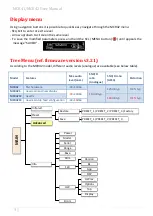
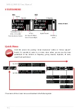
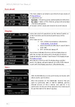
Page 10: ...u can see the main parameters of the receiver as frequency group channel Expander RF level squelch and audio level The screens of the circular menu are described in the following table Status Screen R...

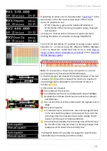
Page 11: ...the third screen are showed the instant RF levels of the two receivers and it is showed the minimum maximum and average value calculated in a time frame of about 4 minutes In this screen are showed th...

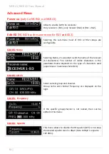
Page 12: ...one and set the max audio level of the outputs LINE max lev 8 12 dBu only for HW rev 21 MIC max lev 30 10 dBu only for HW rev 21 LINE max lev 18 12 dBu only for HW rev 21 AES max lev 30 0 dBFS COM max...

Page 13: ...el BPA42 PTT HPN BAG S1LK 42 SX SLK 42 IK SLK 42 PH BPA42 HPN Alim Type of power supply Ext FW Version FW version v2 0 5 BL Bootloader version v 1 0 18 App Application version v2 5d DSP DSP version v0...

Page 14: ...to edit the name of the receiver 12 characters The number of visible characters in the parameter Name depends on the type of characters used uppercase or lowercase characters Edit RX GR Ch Select curr...

Page 15: ...red to the ENR ENC standard increasing the S N ratio up to 15dB To use these expanders it s necessary to set ENR on the transmitter and ENR 1 2 on the receiver or set ENC on the transmitter and ENC 1...

Page 16: ...e to choose where to put the output between LINE and COM The COM column is present only using the Stand alone socket BPA42 PTT When tone squelch is set to ON it is possible to choose where to put the...

Page 17: ...be set from 18 dBu to 12 dBu in one dB step The max audio level of the AES3 output can be set from 30dBFS to 0dBFS in one dB step Edit RX Sig Phase To change audio phase of 0 deg or 180 deg Edit RX S...

Page 18: ...d guard of 2 digital television channel Edit RX Cal tone If Cal tone is enabled a calibration tone is transmitted from the outputs of the receiver and the audio LED of the relative RX become blue to t...

Page 19: ...sible to set up to 12dB between RX1 RX2 For example if volume is set to 0dB Rx signal to Rx1 Rx2 L R and RX mix to Rx1 6 in the HP output RX1 will be at 3dB and RX2 will be at 3dB RX sel Left and righ...

Page 20: ...ase of alarm only red OFF all LEDs are always off Low timeout indicates the time until the display stays on with the contrast set after which the display contrast is lowered and after another Low time...

Page 21: ...le NOTE1 When the receiver is reset the error information code and error type on the list are lost Errors Message on display A Error type C Code C Low voltage level Battery Low Ext pwr Low TX of RX1 B...

Page 22: ...corrupt copy1 with copy2 RX1 copy2 invalid Error during the initialization phase The CRC 16 check of RX1 data copy 2 detects error no the receiver automatically replace the corrupt copy2 with copy1 R...

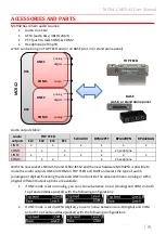
Page 23: ...desired LINE mode inside the advanced menu Analog or AES3 digital different output options are available if LINE mode is set on Analog you can choose between Line A Analog and COM on both Top Feed and...

Page 24: ...CR42 Exx can then be in factory configure to connect on top LINE1 2 or COM 1 2 the audio source you need STAND ALONE ACCESSORIES Line 1 2 to XLR MCR42 ECL PTT Line 1 Audio Line 2 MCR42 ELC Audio Line...

Page 25: ...ne output AES3 48 kHz DC power supply connector Hirose HR10A F pin 1 ground pin 4 Vdc Push to Talk PTT Audio Output Com PTT line output 1 2 electronically balanced on a 5 pin mini XLR Male connector H...

Page 26: ...ween 30 18dBu depending on the Hardware version and 6 dBu nominal and MAX 12 dBu peak deviation Audio line output imped 200 ohm Line 1 2 pinout Shield GND RED cable Positive BLUE cable Negative DC pow...

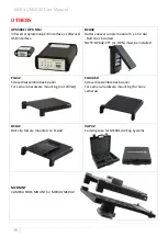
Page 27: ...1 XLR 3M line output isolated with audio tranformer hirose power from camera CAP52 SX STAND ALONE HARNESS CABLE DB15 to MCR42 Sony slot in compatible 2 XLR 3M line output isolated with audio tranform...

Page 28: ...LONE HARNESS CABLE DB25 to MCR42 Ikegami Panasonic slot in compatible 2 XLR 3M line output isolated with audio tranformer hirose power from camera TOP FEED COMPATIBILITY MCR42 41 BPA42 PTT BPA42 HPN S...

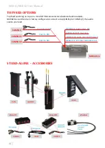
Page 29: ...se 90 deg sma connector Broadband UHF 470 700 MHz black cap 590 label AWM42RA Whip Antenna plastic case 90 deg sma connector Broadband UHF 566 798 MHz yellow cap 670 label AWN42 Whip Antenna plastic c...

Page 30: ...V AA Batteries included NOTE BPA42 PTT or HPN must be installed FLA42 Screw disassemble back panel For camera hardware mounting not drilled FLA42 SX Screw disassemble back panel For camera hardware mo...

Page 31: ...om audio inputs of the camera CD34 connected to camera power source if not using the battery pack MCR42 Line1 2 are configured to analogue output and PTT CAM50 2 Line1 audio 1 connected to XLR 3F anal...

Page 32: ...l input of the camera MCR42 EL2 or MCR42 ECL Analogue Audio 1 thru slot in and Audio 2 thru external XLR 3F CAM50 42 Top feed Line analogue audio 1 connected to XLR 3F 2 analogue external input of the...

Page 33: ...RK950 or MRK960 NOTE the USB drivers must be installed on the PC for further info check on the Download area of the Programmers UPKxx on Wisycom website 2 Check if the version of Wisycom Manager in yo...

Page 34: ...panel 12 characters available and push the Write button underlying How change the name and description of Groups Click and then Right click on a name or description box presents in the Name or Descri...

Page 35: ...esent on the device Note1 If not set the expander is set to DSP_ENR by default Note2 Name and expander selected are the same for all groups For example if Ch 03 Ch name George and EXP DSP_ENC if set G...

Page 36: ...sible to modify for the group name description locked hidden propriety for the channel name expander frequency value and the locked hidden propriety click right mouse button NOTE1 The modifications ar...

Page 37: ...le Save to file menu and decide the name of wdf to save This operation create a wdf file using the channels configuration showed in the central grid it doesn t save the configuration in the MCR41 42 R...

Page 38: ...1 MCR42 User Manual 37 How to update the firmware 1 Push FW upgrade button 2 Download the upf file and load the file using Select button 3 Click on Start FW upgrade 4 Confirm start FW upgrade pushing...

Page 39: ...d later it writes the flash memory A green bar below the panel shows the progress of this process Take care do not disconnect the IR communication or power off the MCR41 42 during this process 7 At th...

Page 40: ...6 dB V 100 dB V Co channel rejection 2 5 dB Adjacent chan selectivity 80 dB typical for ch spacing 400 kHz Spurious rec rejection 100 dB IF image rejection 90 dB Intermod rejection 76 dB IIP3 10 dBm...

Page 41: ...One touch function for a frequency scan and sync function Powering External 5 18 Vdc 1 5 W max Autonomous with optional BCA 42 Battery Module 5 x IEC LR6 1 5V size AA alkaline or rechargeable element...

Page 42: ...o del cassonetto barrato riportato sull apparecchiatura o sulla sua confezione indica che il prodotto alla fine della propria vita utile deve essere raccolto separatamente dagli altri rifiuti La racco...

Page 43: ...MCR41 MCR42 User Manual 42...

Page 44: ...MCR41 MCR42 User Manual 43 Via Spin 156 I 36060 Romano d Ezzelino Italy Tel 39 0424 382605 Fax 39 0424 382733 www wisycom com e mail sales wisycom com...

Reviews: