cyber
®
simco
®
drive 2 operating manual
Revision: 02
5022-D057946
en-19
de
utsch
english
fra
nçais
ita
lia
no
es
pa
ñol
日本語
5.3.2 IP20 mounting options
The drive amplifier may be mounted on a top-hat rail of type TS 35 using the integrated metal
top-hat rail.
Alternatively, the drive amplifier can be connected to the mounting plate using a screw
connection:
Mounting material: 2 cylinder head screws with hexagon socket ISO 4762 - M 4
– 8.8
Required tool: Inner hexagonal bolt SW 3
For tightening torques, see chapter 9.1
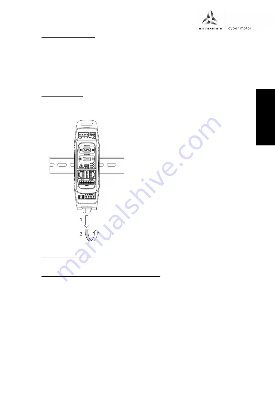
5.3.3 IP20 disassembly
The drive amplifier is disassembled from the top-hat rail by pushing downwards and removing
the drive amplifier. See following figure.
5.3.4 IP20 installation space
The central variant of the drive amplifier is designed for installation in the control cabinet.
5.3.5 IP20 Environmental conditions for vibration/shock
The drive amplifier fulfills the following specifications:
Vibration according to DIN EN 60068-2-6:2008
o
Frequency range 10 Hz
– 150 Hz
o
Acceleration: 1 g
Shock according to DIN EN 60068-2-27:2010
o
Shock form: semi-sinusoidal
o
Acceleration: 15 g
o
Shock duration: 11 ms
Summary of Contents for Cyber Simco Drive 2
Page 1: ...5022 D057946 Revision 02 cyber simco drive 2 Operating manual ...
Page 2: ......
Page 56: ......


