cyber
®
simco
®
drive 2 operating manual
en-32
5022-D057946
Revision: 02
6.6 Connection assignments device version IP20 central SIM20xxD-CC...
6.6.1 Overview of IP20 plug connections
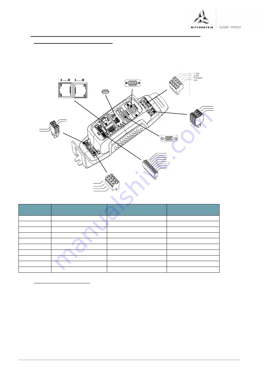
The following illustration shows the arrangement of the plug connections with associated
label on the drive amplifier:
Image 6.3: Overview IP20 plug connections
No.
Function
Connector type on
the device
Connector type on
the cable
X1
Power
Dinkle 5EHDVC-04PL
Dinkle 5ESDF
X2
Logic supply
Dinkle ECH350V-03PL
Dinkle 0181-A303
X3
Resolver interface
D-Sub, 9-pin, female
D-Sub, 9-pin, male
X4
Encoder
D-Sub, 15-pin, female
D-Sub, 15-pin, male
X5
Diagnostic interface
Mini-B socket
Mini-B plug
X6
Input fieldbus interface
RJ45 socket
RJ45 plug
X7
Output fieldbus interface RJ45 socket
RJ45 plug
X8
Digital I/O
Dinkle 0225-3708L
Dinkle 0225-0808
X9
Brake / temp
Dinkle 0159-3204L
Dinkle 0159-0304
X10
Motor
Dinkle 5EHDVC-04PL
Dinkle 5ESDF
6.6.2 IP20 connection diagram
The following illustrations show the key connection diagrams of the drive amplifier when
supplied with SELV and PELV power supply units.
For applications in driverless transport systems (DTS), the standard DIN EN 1175-1
(VDE 0117-1):2011-06 must be applied. If simco
®
drive 2 is to be used in a DTS application,
the wiring illustrated in the following must be used due to missing galvanic isolation between
logic and power. In this respect, simco
®
drive 2 is fully supplied from the battery. This is
enabled by a wide range voltage input of 12-60 VDC and the possible use of a power source
(logic supply is realized via an internal diode).
Deviating from the standard DIN EN 1175-1 (VDE 0117-1):2011-06 chapter 5.7.3 e), ceramic
capacitors (1000 V; with soft termination) are used instead of Y capacitors between the
housing and DC+/DC-. This way, the risk of a short circuit between DC- or DC+ and the frame
with subsequent fire risk is classified as very low.
X5
USB
X10
Motor
X9
Brake/temperature
X8
Digital I/O
X2
Logic
X4
Encoder
X3
Resolver
1 Logic +
2 STO
3 STO GND
3 Phase W
1 Phase U
2 Phase V
4 FE
1 TEMP+
2 BRAKE+
3 TEMP-
4 BRAKE-
1 DOUT2
2 DOUT1
3 DIN4
4 DIN3
5 DIN2
6 DIN1
7 GND
8 VCC24
6 7 8 9
1
6
5
10
11
15
X1
Power
X7
Fieldbus OUT
X6
Fieldbus IN
1 2 3 4 5
Summary of Contents for Cyber Simco Drive 2
Page 1: ...5022 D057946 Revision 02 cyber simco drive 2 Operating manual ...
Page 2: ......
Page 56: ......


