cyber
®
simco
®
drive 2 operating manual
en-38
5022-D057946
Revision: 02
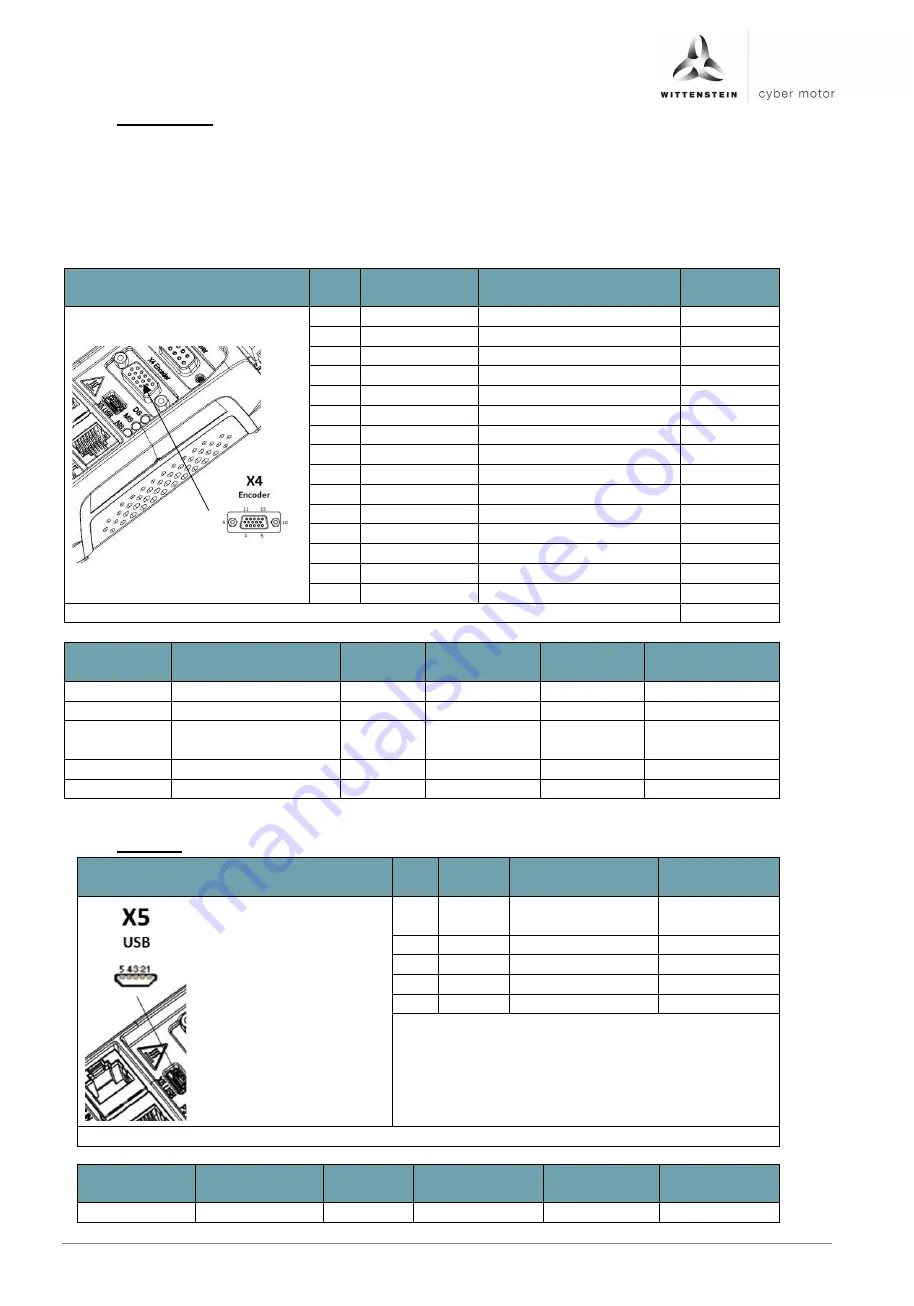
6.6.7 X4: Encoder
The plug may only be inserted when the drive amplifier is in a de-energized state.
Via the encoder interface X4, fully digital encoder systems with the protocols
EnDat 2.2 and BISS C can be evaluated.
The encoder interface has a 5 V power supply, secured with a self-resetting fuse,
with a max. current rating of 500 mA.
Encoder emulation is also available via encoder interface X4.
Figure
Pin
no.
Signal name
Function
Input /
output
1
GND
Ground reference
Output
2
VCC
Encoder power supply
Output
3
CLOCK+
Clock output
Output
4
CLOCK-
Clock output inverted
Output
5
DATA+
Data channel
Input
6
DATA-
Data channel inverted
Input
7
A+
Encoder emulation A+
Output
8
A-
Encoder emulation A-
Output
9
B+
Encoder emulation B+
Output
10
B-
Encoder emulation B-
Output
11
Z+
Encoder emulation Z+
Output
12
Z-
Encoder emulation Z-
Output
13
N. C.
14
N. C.
15
N.C.
Plug type on drive amplifier: D-Sub, 15-pin, female
Connection Feature
Unit
Minimum
value
Nominal
value
Maximum
value
VCC
Output voltage
V DC
4.5
5
5.5
Output current
mA DC
500
A+, A-, B+,
B-, Z+, Z-
Output voltage
V DC
5
Output current
mA DC
42
Output resistance
Ohm
120
6.6.8 X5: USB
Figure
Pin
no.
Signal
Function
Input/
Output
1
+5V
Supply voltage
Input
2
DM
Data +
Input / output
3
DP
Data -
Input / output
4
N.C.
5
GND
Ground reference
Plug type on drive amplifier: Mini-USB B socket
Connection
Feature
Unit
Minimum
value
Nominal
value
Maximum
value
USB 2.0
Summary of Contents for Cyber Simco Drive 2
Page 1: ...5022 D057946 Revision 02 cyber simco drive 2 Operating manual ...
Page 2: ......
Page 56: ......


