cyber
®
simco
®
drive 2 operating manual
Revision: 02
5022-D057946
en-41
de
utsch
english
fra
nçais
ita
lia
no
es
pa
ñol
日本語
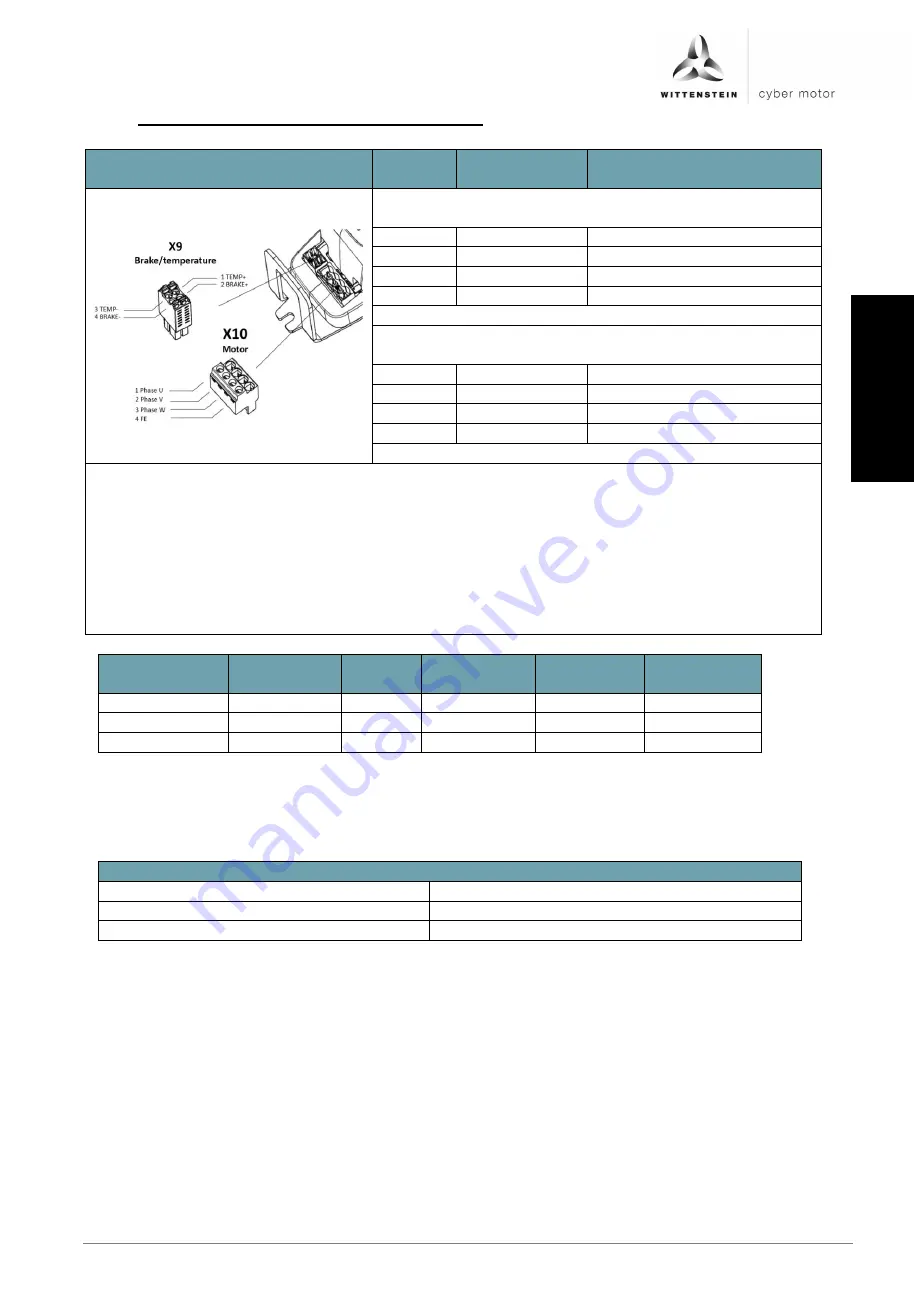
6.6.12 X10: Motor / brake / temperature connection
Figure
Pin no.
Signal name
Function
Motor plug X10
1
PHASE_U
Motor phase U
2
PHASE_V
Motor phase V
3
PHASE_W
Motor phase W
4
FE
Functional earth
Brake/temperature plug X9
1
TEMP+
Motor temperature
2
BRAKE+
Holding brake +
3
TEMP-
Motor temperature sensor -
4
BRAKE-
Holding brake -
Plug type X9 Dinkle 0159-0304
Permissible wire cross-section: AWG 24..26
Stripping length: 8 mm
Plug type X10 on Dinkle 0181-A303
Permissible wire cross-section: AWG 24..12
Stripping length: 8 mm
Tightening torque: 0.5 ... 0.6 Nm; the tightening torque must be 0.5 Nm to conform to the
UL requirement
Connection
Feature
Unit
Minimum
value
Nominal
value
Maximum
value
PHASE_x
Current
Aeff
15
1
/ 7.5
2
30
1
/ 15
2
BRAKE+/-
Voltage
V DC
24
Connection
Current
A DC
0.8
1
: SIM2015D
2
: SIM2007D
The following overview shows the correct wiring of the motor phases of cyber
®
dynamic line
via the adapter cables S/L-cable xxxHI-xxxx-BA0-6/3:
Connection schematic
U
Red
V
White
W
Black
Summary of Contents for Cyber Simco Drive 2
Page 1: ...5022 D057946 Revision 02 cyber simco drive 2 Operating manual ...
Page 2: ......
Page 56: ......


