SP
+
Assembly
Revision: 03
2022-D033540
en-11
z
Smear screw-bonding agent (for example Loctite 243) onto the four bolts (F).
z
Fasten the motor (D) onto the adaptor plate (B) with the four screws (F).
z
Select the tightening torque for the clamping bolt (H) according to the material of the clamping
ring (I).
- Clamping bolt for
steel
clamping ring: Property class 12.9
- Clamping bolt for
aluminum
clamping ring: Property class 8.8
L
For bolt sizes and specified torques refer to chapter 9.1 "Specifications on mounting onto a
motor", tables "Tbl-14".
z
Ensure that the motor is mounted if possible in
a vertical direction.
z
If the motor shaft has a shaft key, remove the
shaft key.
L
If recommended by the motor manufacturer,
insert a half wedge.
z
Remove the plug (A) from the mounting bore in
the adaptor plate (B).
z
Turn the clamping hub (C) until the clamping
bolt (H) can be reached by the mounting bore.
z
Loosen the clamping bolt (H) of the clamping
hub (C) by one revolution.
z
Push the motor shaft into the clamping hub of
the gearhead (E).
L
The motor shaft should slip in easily. If this is
not the case, the clamping bolt must be
loosened more.
L
A slotted bushing has to be installed extra for
certain motor shaft diameters and
applications.
L
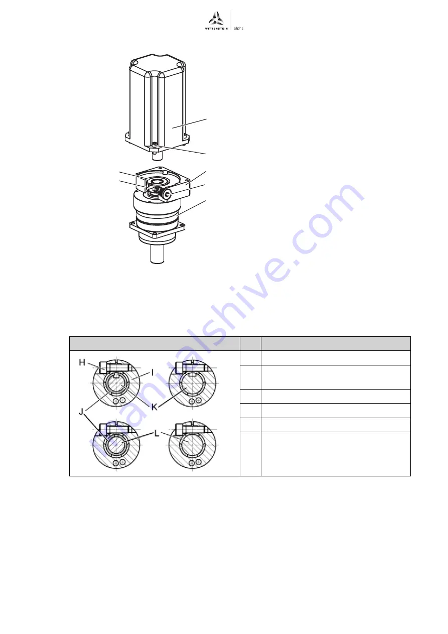
The slot of the bushing (if provided) and
clamping hub have to be flush with the
groove (if provided) of the motor shaft, see
table "Tbl-5".
L
No gap is permitted between motor (D) and
the adaptor plate (B).
Designation
H
Clamping bolt
I
Steel/aluminum clamping ring
[part of the clamping hub (C)]
J
Bushing
K
Keyed motor shaft
L
Smooth motor shaft
Tbl-5: Arrangement of motor shaft, clamping hub, and bushing
A
B
H
C
D
E
F


