µW0001MR49U-FIT$021010250000`Ä
W0001MR49U-FIT$021010250000
Fitting
Instructions
TOWBAR
For Mercedes E Class Estate (W212)
2010-
MR49U
for
MR49 &
MR49Q
MATERIALS
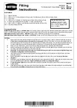
A 1 Main Crossbar
B 4 M10 x 40 x 1.5 Coach Bolts, 4 Flange nuts, Flat Washers (30mm OD) and Nyloc Nuts.
D 2 Side Arms
F 8 M10 x 40 x 1.5 Bolts, 16 Flat Washers (25mm OD) and Nyloc Nuts.
G 2 Witter cage Nut Retainers and M12 x 1.75mm Square Nuts.
H 2 M12 x 45 x 1.75 Bolts, Lock Washer and Flat Washers (30mm OD)
ZE 1 Electrical Plate (SEP M)
For use with either
MR49 Flange neck option
– ZF3022.
Note:
This towbar must be used with either a Witter Towball (part number Z11) or Class
A50-1 or A50-X towball, which dimensionally conforms to A50-
1 with a ‘D’ and 'S' value greater than or equal to that of the towbar.
MR49Q Detachable neck option
– ZQ3022.
Please refer to ZQ fitting instructions for installation
MR49QF Detachable Flange neck option
– ZQF 3022.
Please refer to ZQ fitting instructions for installation
FITTING
1.
Remove the boot mat and the storage bin from the boot. To remove bumper, undo 2 nuts from inside the rear panel.
(These have a long thread so a specialist tool is required.)
Within arch remove 1 screw and two plastic clips for
wheel arch lining and 1 Tip screw. From underside remove 2 bolts and 4 screws. To pull bumper rearward clips must
be eased off/levered downwards between lights and bumpers. Pull rearward disconnecting parking sensor plugs.
2.
Remove inner crash beam , and remove the mounting point plugs from inside the boot chassis rails.
3.
Before inserting side arms
(D)
into chassis rail. Temporarily fit main crossbar
(A).
Using as template cut a slot into the
two back panel seals for side arms and remove crossbar.
4.
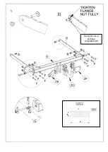
Important: To insert side arms (D) locate coach bolts B into square slots on side arms and tighten flange nut
fully. Refer to diagrams 1 & 2 for orientation.
5.
Insert sides arms into chassis rail aligning with mounting points from boot. Fit washer s and Nyloc Nuts , but leave
arrangement loose.
6.
Before fitting Main cross bar
(A),
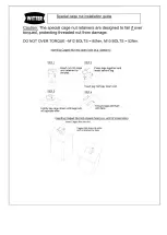
insert captive fasteners
(G)
into both ends of the cross tube
as per Fastener
diagrams
.
7.
Slide Main cross bar
(A)
over side arms (
D)
and fasten to back panel using bolts (
F
). Align side arm slots to main cross
bar using Bolt
H
though captive
(G.)
Tighten all fasteners to their recommended Torque.
8.
To prevent water ingress
seal around the side arm where it passes through the ends of main cross bar with good
quality sealant
9.
Attached preferred neck to the lower set of hole for self levelling or alternatively the higher setting for non self levelling.
Fit electrical bracket
(ZE)
and fully tighten to recommended torque.
Recommended torque
settings:
Grade 8.8 bolts:
M10 - 52 Nm, M12 - 80 Nm,
M16 - 200 Nm
Grade 10.9:
M12
– 120Nm.
Summary of Contents for MR49U
Page 2: ...Serrer l écrou à embase complètement ...
Page 3: ......

