6
Installation instructions Primor 1000
09.11.2012
4.4 Mounting the input unit RO
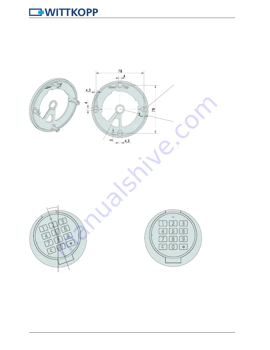
• Mount the input unit with an angle of approx. 20° to the fixing ring – position 1 (see fig. 7) and bring it into position 2 (see
fig. 8) by turning to the right. The turning has to happen easily.
Fig. 8: Position 2 - Mounting input unit
Fig. 7: Position 1 - Mounting input unit
20°
4.3 Installation of fixing ring
• In order to install the fixing ring 4 threaded holes M4 and 1 drilling with max. Ø 11.4 mm/min. Ø 10.5 mm have to be
drilled into the safe door. When mounting the fixed input unit RO, a door hole drilling of Ø 9mm is enough.
• Afterwards the fixing ring has to be fixed with the enclosed cylinder screws M4 x 10 from the front. Do not damage the input
unit when doing this.
Fig. 6: Installation dimensions fixing ring
4 x Fixing position for
screws M4
Middle axis of the input unit con-
gruent with middle axis of nut of the
electronic lock/four cornered shaft of
the boltwork actuator
Opening for cable


