Gearless Lift Machine
WSG-08
with caliper disk brake
Operating Instructions
7.1. General
The electrical connection may only be made
by a qualified electrician.
Before starting any work on the machines,
ensure that the lift machine or system is
properly isolated.
Before making any connections check that
•
the connecting cables are suitable for their specific
application and for the relevant voltages and currents.
•
the sufficiently dimensioned connecting cables and
torsion, strain and shear relief as well as anti-kink pro-
tection are provided
•
the protective conductor (Protection Class I only) is
connected to the earthing terminal
•
there are no foreign bodies, dirt or moisture in the ter-
minal boxes
•
cable entries not in use and the terminal box itself are
tightly sealed to prevent the ingress of dust or water.
The insulation system of the motors is
designed such that they can be connected
to a converter with a maximum d.c. link
voltage U
link max
up to max. 700 Volt.
Note: U
link max
is the maximum value of the
d.c. link voltage which is only transient and
approximately equivalent to the inception
voltage of the braking chopper or of the
energy recovery unit.
The maximum permissible rate of voltage
rise (dU/dt) at the motor terminals may be
max. 4 kV/
m
s.
The overvoltage at the motor terminals
must not exceed 1.56 kV. It may be neces-
sary to use motor current filters or reactors
to achieve these values.
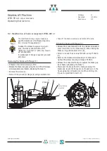
7.2. Motor connection / Winding protection
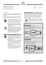
The electrical connection of the motor and the winding
monitoring devices is made in the terminal box on top of
the machine.
Seite/page
10
Datum/date
12.08.2016
Stand/version
0.18
Änderungen vorbehalten! Subject to changes without notice!
7. Electrical connection
Danger
Note
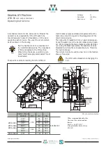
Terminal box for motor connection
1)
When using the nominal cross-sections with ferrules, the usable
cable cross-section is reduced!
Technical data:
Cable cross-section:
...
4
mm
2
(
6
mm
2
with WSG-08.4)
Stripping length required: 9...10 mm
The motor cable must be shielded. Ensure
that the cable shield contacts the frame
over a large area at both ends.
The motor phases U1, V1 and W1 must be
connected correctly to the corresponding
phases of the converter; they must not be
interchanged.
The WAGO terminal strips are suitable for the following
types of copper conductors:
single-core
conductor
fine-stranded
compacted con-
ductor
stranded
conductor
fine-stranded
with ferrule
conductor
1)
fine-strand-
ed conduc-
tor
fine-stranded
with terminal
pin conductor
Caution
Summary of Contents for Beamer 2 Series
Page 36: ......
Page 37: ......
Page 41: ......

