Gearless Lift Machine
WSG-08
with caliper disk brake
Operating Instructions
Seite/page
19
Datum/date
12.08.2016
Stand/version
0.18
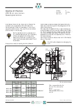
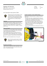
Release lever set with remotely controlled bowden cable
Release lever set with remotely controlled bowden cable
H1
H2
b
handbetätigt
hand-operated
H2
a
fußbetätigt
foot-operated
16
654
403
377
97
14
0
35
2
13
9
2 x
∅
13,5
9.4. Emergency evacuation
The lift design engineer
must always provide
for an electric return
motion control or for
a manual rewinder
(please note EN 81-20).
Should a failure occur
with the car at rest, the car can be
moved with the drive connected to
the mains or to an uninterruptible
power supply (UPS) or mechanically
under its own load with the emer-
gency brakes temporarily released.
These brakes are released electrically
either from the mains or using a
UPS.
They can, however, also be released
manually.
For this purpose the brakes are
equipped with a lever plate (16) into
which two ring bolts (e.g. M8 to
DIN 580) spaced 35 mm apart can be
screwed (see "Release lever set with
remotely controlled bowden cable").
By inserting lever rods (dia. max.
20 mm), the brakes can be released
manually.
The brake lever plates and the asso-
ciated counter plates also have holes
and slots to which Bowden cables
can be attached. By using special
lever devices, the brakes can then
also be released remotely by hand
within certain limits. Such devices
are shown in the figure and table
"Release lever set with remotely
controlled bowden cable" This "lever
system" with 3 m Bowden cables
(preferred length 3 m, max. length
6 m) can be supplied on special order.
If the brakes are released with the
motor deenergised, the motor wind-
ings should be short-circuited. This
prevents the lift from accelerating in
an uncontrolled manner since the
short-circuiting produces a speed-
dependent braking torque.
Änderungen vorbehalten! Subject to changes without notice!
Note
WSG-
08.1/2/3
(two brakes)
08.4
(three brakes)
Item in
figure
Assembly
Number
Item no.
Number
Item no.
H1
bowden cable
2
505 656-2
(
preferred length 3 m)
3
505 656-2
(preferred length 3 m)
H2 a
lever support
1
505 045 900
1
505 045 900
H2 b
lever support
1
505 666
1
505 045
L1
220
390
L2
250
430
U1
76
98
U2
93
140
d3 / L3
Æ
16 / 300
Æ
20 / 400
Summary of Contents for Beamer 2 Series
Page 36: ......
Page 37: ......
Page 41: ......

