Gearless Lift Machine
WSG-08
with caliper disk brake
Operating Instructions
Seite/page
21
Datum/date
12.08.2016
Stand/version
0.18
Änderungen vorbehalten! Subject to changes without notice!
traction sheave types and brake arrangements must be
taken into account in regard to the arrangement of the
return motion device.
Then screw the threaded bolt into an appropriately posi-
tioned threaded hole in the traction sheave using a span-
ner. While releasing the brake magnets, either electrical-
ly or using the brake lever plates, the slide block can be
displaced by turning the corresponding nuts. This turns
the traction sheave.
The bolt can then be moved to a new hole in the traction
sheave, if required.
The lift must be braked when changing the
bolt.
A mechanical return motion device can be fitted at the
operator's own responsibility if the lift needs to be
moved manually in case of a breakdown or if the car is
caught by a safety device. The use of the return motion
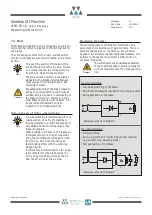
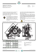
device is shown in the drawing.
Bolt the bearing block to a cross-beam at
the recommended spacing. The cross-beam
is firmly connected to the lift machine.
When fitting the device, a switching com-
mand "electrical supply disconnected" must
be activated.
The specific conditions resulting from the different
Danger
Note
Return motion device
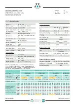
Other recommended values for
the use of the return motion
device:
Angle
a
: ca. 30° to 50°
max. permissible traction force
FZ: 9 kN
traction sheave
X5 X6 X7
ØD
T
B
T
FB
T
WSG-08.1
WSG-08.2
WSG-08.3
4 0 X7
400
60
166
505 382 002
4 S X7
70
176
4 E X7
82
188
4 N X7
90
196
3 S X7
340
70
196
3 N X7
95
221
WSG-08.4
4 T X7
124
284
Summary of Contents for Beamer 2 Series
Page 36: ......
Page 37: ......
Page 41: ......


