Gearless Lift Machine
WSG-08
with caliper disk brake
Operating Instructions
Seite/page
24
Datum/date
12.08.2016
Stand/version
0.18
Änderungen vorbehalten! Subject to changes without notice!
The modification may only be made by a
qualified personnel. Life-threatening situa-
tion in case of misapplication !
To adapt the brakes to special rope guid-
ance, the brake variants "RHS + LHS",
"RHS + top-mounted" or "LHS + top-mount-
ed" are available.
If a subsequent change is required, proceed
as follows:
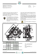
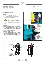
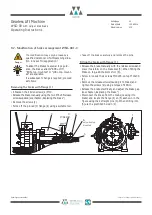
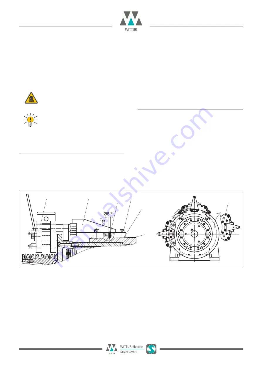
Removing the brake with flange (1)
•
4 Slacken the 4 Allen screws (2) M10.
•
Release the brake manually using the two M6 x 65 release
screws supplied (see chapter „Replacing the brake“)
•
Remove the screws (2).
•
Force off the pinned (3) flange (4) using a suitable tool.
Note
•
Take off the brake carefully and remove the pins.
Fitting the brake with flange (1)
•
Release the brake manually with the release screws and
place it carefully on the brake disc (5). When fitting the
brake on top, add the 4mm shim (6).
•
Screw in loosely the 4 screws M10x25, on top M10x30
(2).
•
Remove the release screws (causing it to brake) and
tighten the screws (2) using a torque of 48 Nm.
•
Release the brake electrically and adjust the brake gap
(see chapter „Replacing the brake“)
•
Disconnect the brake from the mains (causing it to
brake) and locate the flange (4) on (5) as shown in the
figure using the 2 straight pins (3). When drilling into
(5) use the predrilled holes in (4).
9.7. Modification of brake arrangement WSG-08.1-3
Danger
1
4
3
∅
8x 20
2
6
5
1
only when top
mounted
Summary of Contents for Beamer 2 Series
Page 36: ......
Page 37: ......
Page 41: ......


