Technical specifications
INTORQ | BA 14.0177 | 04/2016
15
3.3
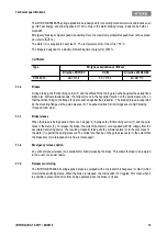
Switching times
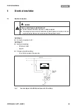
Fig. 2
Operating/switching times of the spring-applied brakes
The transition from the state without brake torque to the steady brake torque is not without delay. The en-
gagement times are valid for switching on the DC side with a spark suppressor (
voltages are five to ten times the rated voltage. The diagram shows the delay time for engagement t
11
, the
rise time of the brake torque t
12
, the engagement time t
1
= t
11
+ t
12
and the disengagement time t
2
.
Disengagement time
The disengagement time is not influenced by DC or AC switching operations.
Engagement time
For emergency braking, short engagement times for the brake are absolutely essential. The DC switching in
connection with a suitable spark suppressor must therefore be provided.
If the drive system is operated with a frequency inverter so that the brake will not be de-energized before the
motor is at standstill, AC switching is also possible (not applicable to emergency braking). In this case, the
engagement times increase approximately by a factor of 5.
t
1
Engagement time
t
11
Reaction delay of engagement
t
2
Disengagement time (up to M = 0.1 M
dyn
)
t
12
Rise time of the braking torque
M
dyn
Braking torque at a constant speed of rotation
U
Voltage
Type
Switching times [ms] at s
LN
Engage
Disengage
t
11
t
12
t
1
t
2
INTORQ BFK466-55
13
20
33
60
Tab. 1:
Switching energy - switching frequency - switching times
Summary of Contents for Beamer 2 Series
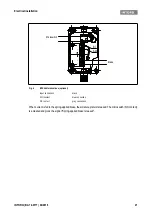
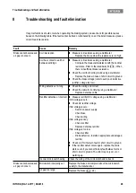
Page 36: ......
Page 37: ......
Page 41: ......


