Gearless Lift Machine
WSG-08
with caliper disk brake
Operating Instructions
The compact flat-type gearless WSG-08 lift machines are
designed for gearless traction sheave lifts with or with-
out a machine room. They are intended for operation
with a 2:1 or 1:1 suspension and are distinguished by
their high efficiency, extremely low noise and excellent
operating characteristics.
The WSG-08 gearless lift machines are designed solely for
use with electronic frequency converters.
The synchronous motor has been designed for various
rated torques, based on a number of overall widths. It
can also be supplied for several rated speeds, which can
then be further adapted to meet individual customer
requirements.
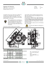
The brake disc is cast onto the spheroidal cast iron rotor
to which the traction sheave (5) is also connected posi-
tively and by frictional contact. The traction sheave is
optimised for customer-specific dimensions and grooves.
Six threaded holes (6) are provided on the front end
periphery, permitting a mechanical return motion device
to be fitted in case of an emergency.
The rotor with shaft (7) is inserted in the stator frame
and supported in a robust self-aligning roller bearing (8)
in the main bearing head and, at the other end, in a sup-
porting ball bearing (9) or, if the traction sheave diame-
ter is 340 mm, in a cylindrical roller bearing. The bearing
is preloaded axially using an ondular washer (10) for
noise reduction. The bearings are sealed on both
sides and life-lubricated. The main bearing has a provi-
sion for relubrication.
The drive-specific measuring system (11) is located within
the centre of the machine behind the ball bearing. It is
connected to the power supply by a signal plug connec-
tor (12). Within certain limits, depending on the motor
dimensions, different measuring systems can be installed.
The electrical connection of the motor is made in the
terminal box (13) where the temperature monitoring
device is also connected.
The EC type-examined brake system comprises two or
three external caliper disk brakes (14), which are con-
nected to the supply voltage via separate brake control
devices. The devices are located in the respective termi-
nal boxes (15), which also accommodate the terminals
for the monitoring contacts. Each brake can thus be
released individually. The brakes can also be released
manually, if required, by fitting lever eye bolts or a Bow-
den cable to the lever plates (16).
The brakes are designed such that in the case of failure
of one brake the remaining brakes are able to decelerate
a car carrying a full payload.
The two rope slip-off guards (18, 19) can also be fitted at
locations 20 and 21 if required.
We would like to refer to the relevant patents held by
KONE Corporation for lifts without machine room.
Seite/page
6
Datum/date
12.08.2016
Stand/version
0.18
Änderungen vorbehalten! Subject to changes without notice!
2. Product description
3. Nameplate
Type code of
lift machine
Rated voltage
Rated speed
Rated torque
Serial no.
Rated frequency
The nameplate of the lift machine is on the motor frame.
Summary of Contents for Beamer 2 Series
Page 36: ......
Page 37: ......
Page 41: ......

