Gearless Lift Machine
WSG-08
with caliper disk brake
Operating Instructions
Seite/page
26
Datum/date
12.08.2016
Stand/version
0.18
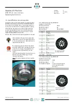
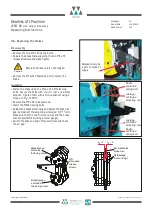
9.9. Replacing the measuring system
The measuring system is only accessible
from the rear side of the motor.
Disassemble the measuring system only if
this is necessary because of a defect.
Remember to readjust the offset value after
reassembly (see the converter operating
instructions).
Disassembly
•
Remove the cable cover from the measuring
system; pull out the cable p.c.b. connector.
•
Loosen the clamping ring on the measuring
system (2 mm Allen screw).
•
Remove the M 5 fastening screw.
•
Insert the M 5 x 45 setscrew to pro-
tect the thread (see figure) and
remove the measuring
system by means of
the M 6 x 50 forcing
screw.
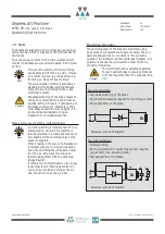
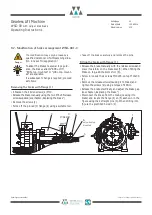
Assembly
•
Check the true running on the stud (plug-in shaft H)
(permissible runout max.0.02 mm).
•
Clean the stud and the measuring system shaft end; do
not grease them.
•
Remove the cable cover from the measuring system.
•
Plug in the measuring system, insert the M5x50 faste-
ning screw in the hollow shaft and tighten the screw
(M
A
= 5,2 Nm)
•
Turn the measuring system so that the cable can be
suitably routed.
•
Tighten the clamping ring on the measuring system
(M
A
=0,65 Nm)
•
Insert the cable p.c.b. connector (observing the desi-
gnation "TOP" or the guiding nose).
The ECN 1313 and ERN 1387 require diffe-
rent cables. Please take this into considera-
tion when replacing the measuring system.
•
Reinstall the cable cover.
•
Fasten the coupling using the clamp and the M5x16
screw.
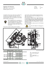
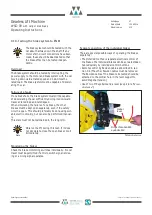
M 5 x 12 (3x)
clamping sleeve
WK 505 626
ECN 1313 /
ERN 1387
M 5 x 50
plug-in shaft H
505 369
M 4 x 10
(3x)
17-pole coupling
AKUA 034.MR04
10 0005 000
cable
Note
Spannring am
Mess-System
clamping ring on
measuring system
Kabelabdeckung
cable cover
Mess-System
measuring system
Anschluss-
kupplung
coupling
Warning
Note
Änderungen vorbehalten! Subject to changes without notice!
Summary of Contents for Beamer 2 Series
Page 36: ......
Page 37: ......
Page 41: ......


