M
3~
U1
V1 W1
PE
T1
T3
T2
T4
S1
S3
S2
S4
L
N
υ
υ
υ
υ
υ
υ
υ
M
M
16
C
M20x1.5
M75x1.5
U1
V1
W1
M20x1.5
Gearless Lift Machine
WSG/WGG-29
Operating Instructions
Code
GM.8.002662.EN
Date
04.02.2019
Version
0.19
Page
10
Subject to changes without notice ! Subject to changes without notice !
EN
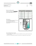
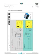
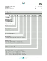
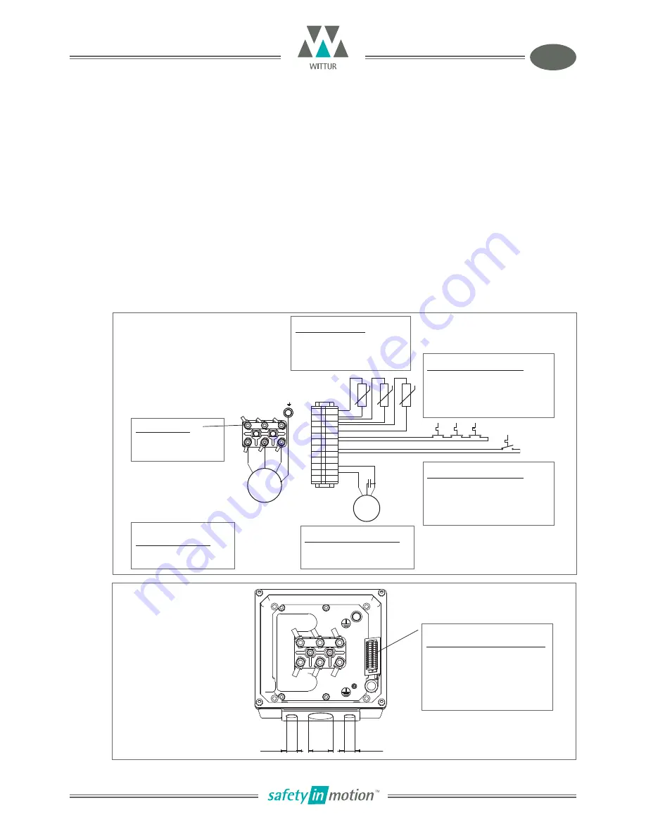
4.2.2. Motor connection / Winding protection / Separately driven fan
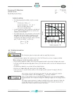
• The electrical connection of the motor, the separetely driven fan and the winding sensors to the mains is
made in the motor terminal box.
• The motor cable must be shielded. Ensure that the cable shield contacts the frame over a large area at both ends.
• The motor phases U1, V1 and W1 must be connected correctly to the corresponding phases of the inverter;
they must not be interchanged.
• We recommend using a inverter with a switching frequency of 8 kHz.
• The thermocouples installed in the winding such as PTC thermistor detectors and thermostatic switches must
be evaluated in the control system or frequency inverter to protect the motor from overtemperature.
• The separately driven fan must be properly connected and operated. If required, it can be switched in
dependence of the temperature by means of thermal switch S4 (relay must be used).
Terminal strip for fan and
winding protection connections
WAGO 260
Cable cross-section:
1,5 mm
2
Stripping length required:
8-9 mm
Terminal box -
screwed cable entry
2 x tapped hole M 20 x 1,5
1 x tapped hole M 75 x 1,5
Separately driven fan
F
D2E 146 AZ03-
230 V / 50 Hz / 1,44 A
Thermostatic switch
S4
1 x S02.60.05 ... (60°C)
(250 V AC / 2,5 A / cos
= 1)
- embedded in the motor winding
- e. g. for fan control
Thermostatic switch
S1
3 x S01.130.05 ... (130°C)
(250 V AC / 2,5 A / cos
= 1)
- embedded in the motor winding
- pre-warning overtemperature
PTC Thermistor
T
3 x STM-150.ES ... (150°C)
- embedded in the motor winding
- for motor protection
Terminal studs
M 16 (max. tightening
torque: 30 Nm)


