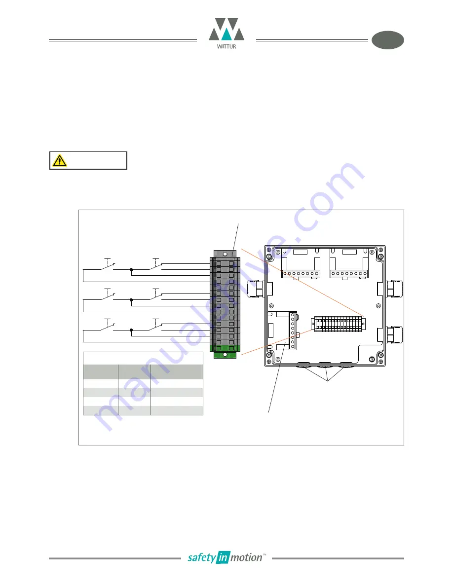
3ö
3s
3e
3w
2ö
2s
2e
2w
1w
1e
1s
1ö
1
2
1
4
2
4
1
2
4
1
4
2
1
2
1
4
2
4
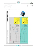
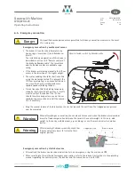
BCD-1
BCD-2
BC
D
-3
3ö 3s 3e 3w
2ö 2s 2e 2w
1ö 1s 1e 1wPE
Gearless Lift Machine
WSG/WGG-29
Operating Instructions
Code
GM.8.002662.EN
Date
04.02.2019
Version
0.19
Page
14
Subject to changes without notice ! Subject to changes without notice !
EN
Monitoring the brakes
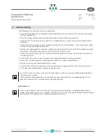
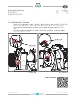
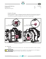
• The switching states and the wear of the brakes are monitored by means of dust-proof microswitches (see
connecting diagram).
• Please assure that the contact-current is at least 10 mA to keep the contacts clean.
Connection of the brakes
The brake coils, the brake control units and the monitoring contacts are connected to the mains in the
brake terminal box.
Warning
The microswitches must be evaluated separately for each partial brake to ensure compliance
with the requirements of the type examination.
WAGO 260
Cable cross-section:
1,5 mm
2
Stripping length required:
8-9 mm
Screw plugs 3 x M 20
Brake monitoring
not applicable
with two brakes
wear
monitoring
*)
release
monitoring
Switching states of the monitoring switches
brake
lining worn
brake
released
Electrical circuit
between
_ö
and
_w
no
no
closed
no
yes
open
yes
no
open
yes
yes
open
*)
The micro switch of the wear monitoring is tripped
in case of unworn and closed brake!


