Installation and Operational Instructions for ROBA
®
-diskstop
®
Type 894.5_ _._ _ Size 10
(B.8.4.5.EN)
23/03/2017 TK/TL/GC/SU
Chr. Mayr GmbH + Co. KG
Eichenstraße 1, D-87665 Mauerstetten, Germany
Tel.: +49 8341 804-0, Fax: +49 8341 804-421
Page 11 of 16
www.mayr.com
, E-Mail:
info@mayr.com
Application
ROBA
®
-diskstop
®
for use as a holding brake with
occasional EMERGENCY STOP braking actions
The max. permitted peripheral speed and friction work (see
Technical Data) must be observed.
Design
The ROBA
®
-diskstop
®
is a spring applied, electromagnetically
releasing safety brake - a component in terms of DIN VDE 0580.
It is designed for installation into gearless elevator machinery for
use as a holding brake with occasional EMERGENCY STOP
braking actions.
On dimensioning, the braking torque, the speed as well as the
permitted friction work in case of EMERGENCY STOP need to
be taken into consideration for safe holding of the load torque
and safe compliance with the required braking distance.
Furthermore, the ROBA
®
-diskstop
®
can be used as a braking
device acting on the shaft of the traction sheave, as part of the
protection device against overspeed for the car moving in
upwards direction and as a braking element against unintended
car movement.
For a dual-circuit brake system, at least two brakes are
necessary.
Please also observe the Annex in the EU Type Examination
Certificate.
In order to guarantee the maximum braking distance while both
brakes act, an inspection of the protection device including all
control and brake times (detector / control / brake) is necessary.
The respective standards, regulations and directives must be
observed.
Function
The ROBA
®
-diskstop
®
brake is a spring applied, electromagnetic
safety brake.
Spring applied function:
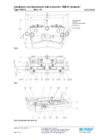
In de-energised condition, the thrust springs (8) press the
armature disk (2) against the brake disk. The brake disk is held
between the friction pads (4).
Electromagnetic function:
Due to the magnetic force of the coil in the coil carrier (1), the
armature disk (2) is attracted against the spring pressure to the
coil carrier (1).
The brake is released and the brake disk can rotate freely.
Safety brake function:
The ROBA
®
-diskstop
®
brakes reliably and safely
in the event of a power switch-off, a power failure or an
EMERGENCY STOP.
Scope of Delivery / State of Delivery
The brakes are manufacturer-assembled ready for installation.
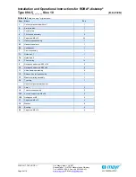
The release monitoring and wear monitoring devices (Items 12
and 13) are set manufacturer-side.
Included loose in delivery are the hexagon head screws (10).
Please check the scope of delivery according to the Parts List as
well as the state of delivery immediately after receiving the
goods.
mayr
®
will take no responsibility for belated complaints.
Please report transport damage immediately to the deliverer.
Please report incomplete delivery and obvious defects
immediately to the manufacturer.
Installation Conditions
CAUTION
Please observe precisely the following
installation conditions and the brake
installation instructions described on page 12.
If the conditions and instructions are not
observed, this might result in premature brake
wear or a substantial loss in braking torque up
to total failure of the brake.
Before mounting the brake, please observe:
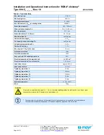
Axial run-out deviation of the brake disk: max. 0.2 mm
Due to axial run-out deviations or tilting
between the brake and the brake disk, the
brake disk may rub against the friction linings.
Brake disk surface quality (friction surfaces): Ra = 3.2 µm
Brake disk material: steel or cast iron.
Brake disk width (25
– 30 mm) acc. respective drawing with
tol0 / -0.15 mm.
There must be a gap of at least 2 mm between the pad (7)
and the counterplate (3) as well as between the pad (7) and
the armature disk (2).
Brake disk deformation or bearing backlash must not
influence the set air gap.
The screw-on surfaces in the
50 mm range
must be 0.1 mm parallel to the brake disk.
Keep the brake surfaces and the friction linings grease-free.
Positional tolerance for installation threaded holes:
0.5 mm.
Please make sure there is a suitable protective cover for
the open brake.
The screw connection must transmit the occurring
transverse forces safely.
The tensile strength R
m
of the attachment wall must be at
least 300 N/mm².
The screw-in depth of both fixing screws (10) must be at
least 25 mm.
Brake Temperature
DANGER
At an ambient temperature of
+40 °C and a duty cycle of 60 %, the brake can
heat up to +65 °C.
Do not touch the brake
=> Danger of burns!

