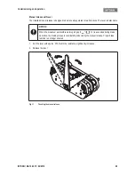
Mechanical installation
INTORQ | BA 14.0201 | 04/2016
18
4
Mechanical installation
Important notes
4.1
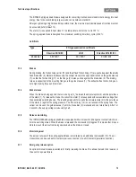
Necessary tools
4.2
Assembly
4.2.1
Preparing the installation
1. Unpack the spring-applied brake.
2. Check for completeness.
3. Verify the nameplate data (especially the rated voltage).
NOTICE
Do not lubricate the screws with oil or grease.
Type
Torque
wrench
Insert for hexagon
socket screws
Transport screw
Cross-tip
screwdriver
Measurement range
[NM]
Width across flats
[mm]
Wrench width [mm]
Cross-tip size
BFK466-61
250
14 x 1/2" square
6 x 1/4" square
2
Multi-meter
Calliper gauge
Feeler gauge
Mechanical installation
INTORQ | BA 14.0201 | 04/2016
19
4.3
Installation
The brake is delivered preassembled with two transport safety bolts (17).
1. Fit the guide sleeve (19) on the drive and tighten it lightly with the fixing screw (21).
2. Use a through-hole and push the brake onto the guide sleeve until the friction faces are in alignment with
the brake disc (20).
3. Turn the brake around the guide sleeve (19) and position the brake radially over the brake disc (20).
4. Push the second guide sleeve (19) into the second through-hole of the brake and tighten it with the fixing
screw (21).
5. Tighten the two fixing screws (21) to the specified torque (
14).
6. Remove locking screws (17) that secure the device during transport!
7. Switch the current on and off several times, checking the movability of the brake on the guide sleeves.
8. Check the clearance of the brake disc and the air gap "s
L
" between the two friction linings (3.2) and the
brake disc (20) using a feeler gauge (24).
Fig. 4
Procedure for installing the BFK466-61 spring-applied brake
NOTICE
The sum of the measured gaps may not be larger than "s
Lmax
"!


