Maintenance and repair
INTORQ | BA 14.0201 | 04/2016
32
7.2
Inspections
Important notes
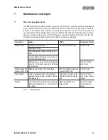
To ensure safe and trouble-free operations, the spring-applied brakes must be checked at regular intervals
and, if necessary, be replaced. Servicing will be easier at the plant if the brakes are made accessible. This
must be considered when installing the drives in the plant.
Primarily, the required maintenance intervals for industrial brakes result from their load during operation.
When calculating the maintenance interval, all causes for wear must be taken into account,
32. For
brakes with low loads (such as holding brakes with emergency stop function), we recommend a regular in-
spection at a fixed time interval. To reduce costs, the inspection can be carried out along with other regular
maintenance work in the plant.
Failures, production losses or damage to the system may occur when the brakes are not serviced. Therefore,
a maintenance strategy that is adapted to the particular operating conditions and brake loads must be de-
fined for every application. For the spring-applied brakes, the maintenance intervals and maintenance oper-
ations listed in the table below must be followed. The maintenance operations must be carried out as
described in the detailed descriptions.
7.2.1
Maintenance intervals
The spring-applied brake must be checked during the prescribed inspections of the drive system in which it
is installed.
❚
The service life of the brake before replacement does not only depend on the number of emergency
brakings.
❚
The wear of the brake friction linings varies depending on the operating conditions.
❚
The friction work possible before replacement decreases with every braking when the switching energy
increases.
7.2.2
Checking the air gap
1. Switch on the current for the brake (see
25).
2. Use a feeler gauge to check the air gap "s
L
" between the brake disc and friction lining. It must not exceed
the maximum permissible air gap "s
Lmax
", as specified in the table (
14).
3. Switch off the current.
4. Reconnect the motor.
DANGER
Make sure that you remove all loads from the drive. Otherwise, there is a risk of an accident.
The motor must not run while the spring-applied brake is being checked.
Maintenance and repair
INTORQ | BA 14.0201 | 04/2016
33
7.2.3
Braking torque / delay check
In case of drives with several brakes, one brake at a time can be released with the socket head cap screws
of the transport safety device or the manual release when checking redundancy. These screws must be re-
moved again after checking.
The stopping distances of the drive must be within the permissible tolerance range of the corresponding fa-
cility (
, Operating Instructions for the facility).
7.3
Maintenance
The brake does not require any maintenance when it is being used as a holding brake. The brake is replaced
in the reverse order of the assembly (
18).
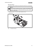
1. Screw in the transport screws (17; DIN912 M8x70) (
19).
2. Switch off the power supply and disconnect the connecting cables.
3. Loosen a fixing screw (4) and remove the guide sleeve (2) from the through-hole.
4. Turn the brake around the second guide sleeve (2) away from the brake disc (3).
5. Remove the brake from the guide sleeve (2).
7.4
Ordering spare parts
INTORQ BFK466-61 spring-applied brake
NOTICE
The screws of the transport locking device must not be used for releasing the brake during
evacuation!
DANGER
Make sure that you remove all loads from the drive. Otherwise, there is a risk of an accident.
The motor must not run while the spring-applied brake is being checked.
Order quantity
Pieces
Size
61
Voltage
90 / 45 VDC
110/55 VDC
205/103 VDC
Cable length
Standard
mm (from 100-1000 mm in 100 mm steps, from 1000-
2500 mm in 250 mm steps)
Terminal box mounted
PTC sensor
Manual release mounted


