Mechanical installation
INTORQ | BA 14.0210 | 12/2016
24
Assembly of the rotor
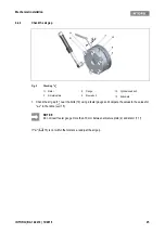
Fig. 7
Mounting the hub onto the shaft
1. Push the complete rotor (3) onto the hub (4) and check that it can be moved by hand. Do not use any
lubricant! (Exception: rotor with toothing that has been sprayed by the manufacturer.)
In the following sections, only assembly for the versions with flange will be described.
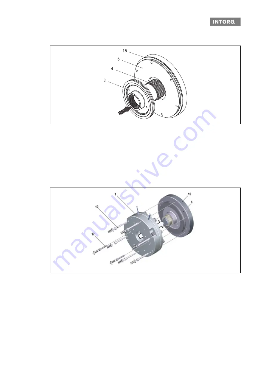
Assembly of the complete stator
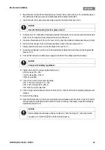
Fig. 8
Mounting the complete stator
1. Push the complete stator (1) onto the shaft.
2. Screw the complete stator (1) into the bearing shield (15) using the bolts (10)
3. Remove the transport safety bolts (17) (discard them).
3
Complete rotor
6
Flange
4
Hub
15 End shield
1
Stator, complete
15 End shield
6
Flange
17 Transport safety bolts (2 or 4 bolts)
10 Cylinder head bolt
Summary of Contents for WSG-TB.3 series
Page 29: ......
Page 30: ......
Page 31: ......
Page 33: ......
Page 37: ......
Page 38: ......
Page 39: ......
Page 43: ......
Page 44: ......
Page 45: ......
Page 46: ......
Page 47: ......
Page 95: ...Notes INTORQ BA 14 0197 04 2016 48 Notes...
Page 144: ...Notes INTORQ BA 14 0210 12 2016 48 Notes...
Page 145: ...Notes INTORQ BA 14 0210 12 2016 49...
Page 146: ...Notes INTORQ BA 14 0210 12 2016 50...
Page 147: ......


