Mechanical installation
INTORQ | BA 14.0197 | 04/2016
29
4.4.6
Manual release assembly (optional)
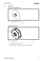
Abb. 12
Assembly of the manual release
1. Insert four stud bolts (12.4) into the bore holes of the transport safety bolts which have been removed.
Tighten with a screwdriver.
2. Put the lever (12.1) onto the brake (14).
3. Place four cup springs (12.6) in alternate directions in each of the four sleeves (12.7). Finally, insert the
sleeves into the holes in the lever (12.1).
NOTICE
The assembly of the manual release is done to the spring-applied brake which is already fitted
to the bearing shield
24. The air gap of the brake is set to the rated air gap,
12.1 Lever
12.6 Cup springs
12.8 Nuts
12.4 Stud bolts
12.7 Sleeves
14 Brake
Summary of Contents for WSG-TB.3 series
Page 29: ......
Page 30: ......
Page 31: ......
Page 33: ......
Page 37: ......
Page 38: ......
Page 39: ......
Page 43: ......
Page 44: ......
Page 45: ......
Page 46: ......
Page 47: ......
Page 95: ...Notes INTORQ BA 14 0197 04 2016 48 Notes...
Page 144: ...Notes INTORQ BA 14 0210 12 2016 48 Notes...
Page 145: ...Notes INTORQ BA 14 0210 12 2016 49...
Page 146: ...Notes INTORQ BA 14 0210 12 2016 50...
Page 147: ......

