Gearless Lift Machine
WSG-W8
Operating Instructions
Seite/page
20
Datum/date
29.01.2010
Stand/version
0.13
Änderungen vorbehalten!
Subject to changes without notice!
9.3. Lubricating instructions
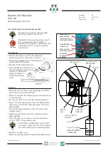
The two traction sheave main bearings (internal and
external self-aligning roller bearings 10 and 12 in the
picture page 7) have been factory-greased with a grease
quantity sufficient for the nominal service life of the
machine. No greasing is required or indeed recommended
under normal service conditions.
In special cases, e.g. under extreme conditi-
ons (maximum utilisation of permissible
axial forces at max. nominal speed), grea-
sing is permitted as follows:
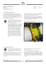
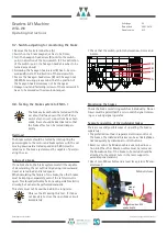
Internal main bearing (10): Screw the lubri-
cating nipple which is "parked" in a dummy
hole on the right motor foot (viewed facing
the traction sheave) into the greasing hole
which is located near the rotor centre. (See
picture "greasing nipple"). Before doing
this, remove the plug screw DIN 908-B-
M10x1 which protects the greasing hole.
To grease the external main bearing (12),
carefully remove the outer bearing cover
(13). Press a small quantity of grease into
the bearings. Then refit the bearing cover
(13) firmly and snugly, close the greasing
hole with the plug and "park" the greasing
nipple.
Note
Greasing nipple
Observe a high standard of cleanliness when doing this
work, to prevent any foreign material, dirt or dangerous
liquids from penetrating into the bearings.
Use a KP 2 N-30 grease to DIN 51 502 (e.g. Wälalit LZ2 or
Klüberlub BE 41-542). The refilled grease should exert
only a slight pressure on the grease column. Therefore
use only a small quantity, max. 0.5 cm
3
.
The NDE secondary bearing is life-lubricated and is not
provided with a greasing facility.
9.4. Emergency evacuation
The lift design engineer must always pro-
vide for an electric return motion control
or for a manual rewinder (please note EN
81-1 / 12.5.2).
Should a failure occur with the car at rest, the car can be
moved with the drive connected to the mains or to an
uninterruptible power supply (UPS) or mechanically
under its own load with the emergency brakes temporar-
ily released.
These brakes are released electrically either from the
mains or using a UPS.
They can, however, also be released manually.
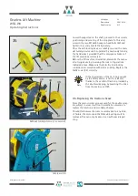
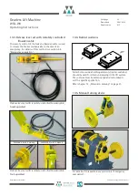
For this purpose the brakes are equipped with a lever
plate (19) into which two ring bolts (e.g. M8 to DIN 580)
spaced 35 mm apart can be screwed (see
"Release lever
set with remotely controlled bowden cable"). By inserting
lever rods (dia. max. 20 mm), the brakes can be released
manually.
Note

