Gearless Lift Machine
WSG-W8
Operating Instructions
Seite/page
24
Datum/date
29.01.2010
Stand/version
0.13
Änderungen vorbehalten!
Subject to changes without notice!
9.6. Replacing the brakes
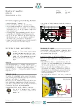
Disassembly
•
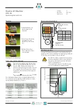
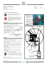
Remove the two M6 x 40 spring bolts.
•
Release the brake manually using the two M6 x 65
release screws supplied (see figure).
Ensure the brake unit is not dropped.
•
Remove the M12x140 fastening bolts; remove the
brake.
Assembly
•
Fasten the brake using the M12 x 140 M fastening
bolts. Secure the bolts with
"omnifit 100" or a similar
product. Tighten them with a torque spanner using a
torque of M
A
= 115 Nm.
•
Remove the M6 x 65 release screws !
•
Insert the M6x40 spring bolts.
•
Release the brake electrically and adjust the brake air
gap by means of the adjusting screws (s
B
= 0,5
+0,1
mm).
Make sure that the two friction linings and the brake
disc are symmetrical (using a feeler gauge).
•
Switch the brake on and off several times and check
the air gap.
Caution
Lüft-
schrauben
release
screws
Bremsscheibe
brake disc
Reibbeläge
friction linings
Befestigungs-
schraube
fastening screw
s
B
/ 2
s
B
/ 2
Befestigungs-
schraube
fastening screw
Feder-
schraube
spring bolt
Justage-
schraube
adjusting screw
Justage-
schraube
adjusting screw
Feder-
schraube
spring bolt
Release screws be
a part of scope of
supply.


