Gearless Lift Machine
WSG-W8
Operating Instructions
Seite/page
25
Datum/date
29.01.2010
Stand/version
0.13
Änderungen vorbehalten!
Subject to changes without notice!
9.8. Testing the brake system to EN 81-1
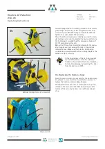
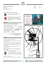
Ringschrauben M
8
eyebolts M
8
Hebel
lever
The brake system should be tested with the
car about halfway down the shaft. If any
motor short-circuit connections have been
made, these should be deactivated so that
the brake effect can be tested indepen-
dently.
Overload
The brake system should be tested by interrupting the
power supply to the motor and brake system with the car
moving downward at rated speed and
1.25
times the
rated load. The brake system must be capable of deceler-
ating the car.
Failure of a brake
If one brake fails, the brake system must still be capable
of decelerating the car sufficiently during its downward
travel at rated load and rated speed.
When simulating the failure of one brake, the other brakes
must be kept open separately, even if the safety circuit is
open. This should preferably be done using suitable electric
circuitry, but can also be performed manually.
This state must not be maintained in the long term.
Observe the lift during this test. If it does
not decelerate, close the open brake circuit
immediately.
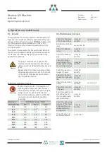
Note
Monitoring the brakes
Check the brake monitoring switches individually. No car
travel must be permitted if a micro switch signal is miss-
ing or a wrong signal operates.
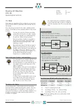
Separate operation of the individual brakes
There are several possible ways of operating the brakes
separately:
•
The preferred method is separate electrical control of
the brakes. The individual brakes can be activated/deac-
tivated quickly by individual control buttons.
•
Remote control by Bowden cable as described in sec-
tion 9.4. (The other Bowden cables must be removed.
The Bowden cable of the brake to be tested should be
attached to the central hole in the lever support to
avoid diagonal tension.)
•
Use of two M8 eyebolts and a lever (see picture
"Manu-
al release").
Manual release
Note
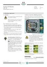
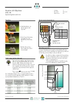
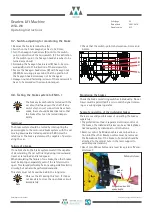
9.7. Switch-adjusting for monitoring the brake
•
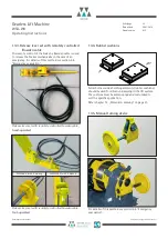
Remove the brake terminal box (A)
•
Switch on the brake magnet; s
B
has to be 0 mm.
•
Turn the hexagon head screw (B) until to the switch-
point in direction of the microswitch (C). For definition
of the switch-point, the hexagon head screw has to be
turned very slowly!
•
Following the hexagon head screw (B) has to be scre-
wed additional 60° in direction of the microswitch.
•
Secure the hexagon head screw (B) with hexagon nut
(D). While securing please mind, that the position of
the hexagon head screw may not be changed.
•
Hexagon nut and fastening-screws of the mocroswitch
have to be secured with screw-lock-lacquer.
•
Check that the switch-point is between s
B
= 0 mm and
0.3 mm.
A
C
B
D


