Gearless Lift Machine
WSG-W8
Operating Instructions
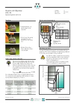
The series WSG-W8 is a complete drive system, including
a base frame (1), an integrated drive motor (2) and a
secondary sheave system (3) for the preferred option of
double wrapping. Different secondary sheave systems
allow for a variety of rope centre distances, as far as is
technically feasible. The three-phase synchronous drive
motor (2), which forms a single unit with the base frame,
is a reliable gearless flat-type motor (2) with an external
rotor. It is distinguished by its high efficiency, extremely
quiet operation and excellent operating characteristics.
All our gearless lift machines are designed solely for use
with electronic frequency converters.
The "W8" system uses two motor widths, W8.3 and W8.4,
with different rated speeds and different traction sheave
diameters. Several rated speeds are available which can
then be further adapted to individual customer require-
ments.
The permanent field flat-type synchronous motor (2)
comprises the sturdy stator frame with stable feet and
the rotor (4).
The frame carries the wound stator core (5), against its
inner surface, and envelops the core to form a pot-like
enclosure. The magnet ring (6) comprising 24 poles (Neo-
dym-iron-boron magnets) rotates within this enclosure.
It transmits the motor torque to the rotor (4) to which it
is attached.
The brake disc (7) is cast onto the spheroidal cast iron
rotor.
The rotor (4) with the brake disc (7) and the traction
sheave (8) are shrunk onto the shaft (9) positively and by
friction contact. The shaft runs in the main bearings (10
and 12) of the traction sheave.
The self-aligning roller bearing (10) inside the motor is a
locating bearing, whereas the outside self-aligning roller
bearing (12) is designed as a non-locating bearing with a
wave spring washer for noise reduction.
The ball bearing (11) located on the flexible shaft exten-
sion is used as a supporting bearing for installing the
motor.
All bearings are sealed on both sides and life-lubricated.
The main bearings (10 and 12) can be greased, bearing 10
through a greasing nipple and 12 by removing the outer
bearing cover (13).
The drive-specific measuring system (14) is arranged wit-
hin the centre of the machine behind the NDE ball
bearing (11). It is connected using a plug connector (15).
Different types of measuring systems can be offered.
The motor is electrically connected in the terminal box
(16), where the connection for the temperature monito-
ring device is also located.
The brake system comprises two (W8.3) or three (W8.4)
external multiple pole clasp brakes (17) which are con-
nected to the power supply via separate brake control
devices. The devices are located in the respective brake
terminal boxes (18) which also accommodate the termi-
nals for the monitoring contacts. Each brake can thus be
released individually. The brakes can be released manual-
ly, if required, by fitting lever eye bolts or a Bowden
cable to the lever plates (19).
The two rope slip-off guards (20, 21) attached to the
motor can be rotated to a large extent. They can also be
fitted at locations 22 and 23 if required.
The secondary sheave system (3), which is available in
different variants, is screwed under the frame plate (1),
and comprises the lateral bearing brackets (26), axle (27),
spheroidal cast iron secondary sheave (28), two sealed
and life-lubricated ball bearings (29) and two settings
rings (30). Rope slip-off guards (31) and a safety brace
(32) are also fitted to the frame plate.
As shown in sections 10 to 12, a number of variants with
differently spaced traction and secondary sheaves are
available. The standard version is the "K" version (type
code X6=K) shown in section 12 (dimension drawing),
which has additional supporting feet to the left and right
of the secondary sheave. As a result, the entire machine
is supported by 5 feet.
If the customer so requests, the frame plate can also be
extended at the secondary sheave end (24). Four feet can
then be fitted below the frame plate, or the frame plate
can be supported on the shaft head without feet.
All holes required for fitting secondary sheaves, supports
or beam bearing surfaces are factory-drilled and can be
used flexibly. The secondary sheave systems are secured
in such a way as to allow for a right or left hand alterna-
tive which can even be changed on site, and which also
permits the offset between the traction and secondary
sheaves to be adjusted. Normally it should be half the
rope centre distance, i.e. a
R
/2.
Seite/page
6
Datum/date
29.01.2010
Stand/version
0.13
Änderungen vorbehalten!
Subject to changes without notice!
2. Product description


