21.05.2015
E
Gearless Synchronous Lift Machines
WSG09.X
Operating and maintenance manual J40003
Page 19
Date
Version
Subject to changes without notice!
(emergency stop) or during an inspection from the d.c. side,
since this ensures a faster braking effect with the car being
stopped earlier.
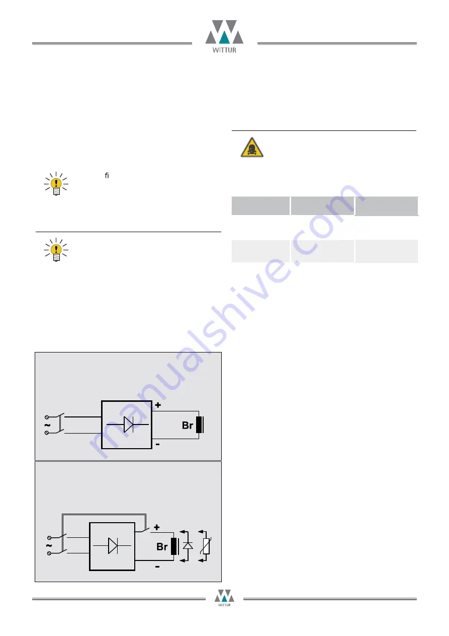
It is therefore recommended to use 2 separate
contactors for
the brake control circuitry ,
one of which switching at the d.c.
side, the other one at the a.c. side.
D.c. side switching
r
Noisy switching.
r
Burn-up protection for switching contact required.
(e.g. varistor, free-wheeling diode)
r
Fast application of the brake.
A.c. side switching
r
Low-noise switching of the brake.
r
No protective measures required for switching contact.
r
Slow application of the brake.
Attention: schematic diagram!
Attention: schematic diagram!
10.4. Brake
The brakes are supplied and held with
110V DC .
75-80V DC
.
The recti er has to be prepared by customer.
Following is two recommend solution for the
brake switching which must be realized by the
control circuit from customer controller.
Note on the use of d.c./a.c. side switching:
A.c. side switching is recommended for nor-
mal operation, since the lift machine is then
decelerated in a controlled manner to zero speed
and the switching noise of the brake is negligible.
Note
Note
for holding voltage is preferred for best performances in tem
-perature rise.The connecting contacts for the micro-switches
which monitor the brakes are also accommodated in this term
-inal box.
Monitoring the brakes
The switching state of the brakes is monitored
using dust-proof micro switches with gold
contacts. Both NC and NO contact is prepared
in terminal box. Please refer the connection
advice in the box for connecting according to
request of the control system as following,
Connect
Power on
the brake
Power off
the brake
C1-O1
C2-O2
open
close
C1-S1
C2-S2
close
open
Danger


