WLKATA Mirobot Manipulator User Manual
Document version 1.0 User Manual Copyright© Beijing Tsinew Technologies Co., Ltd.
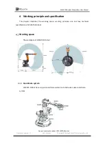
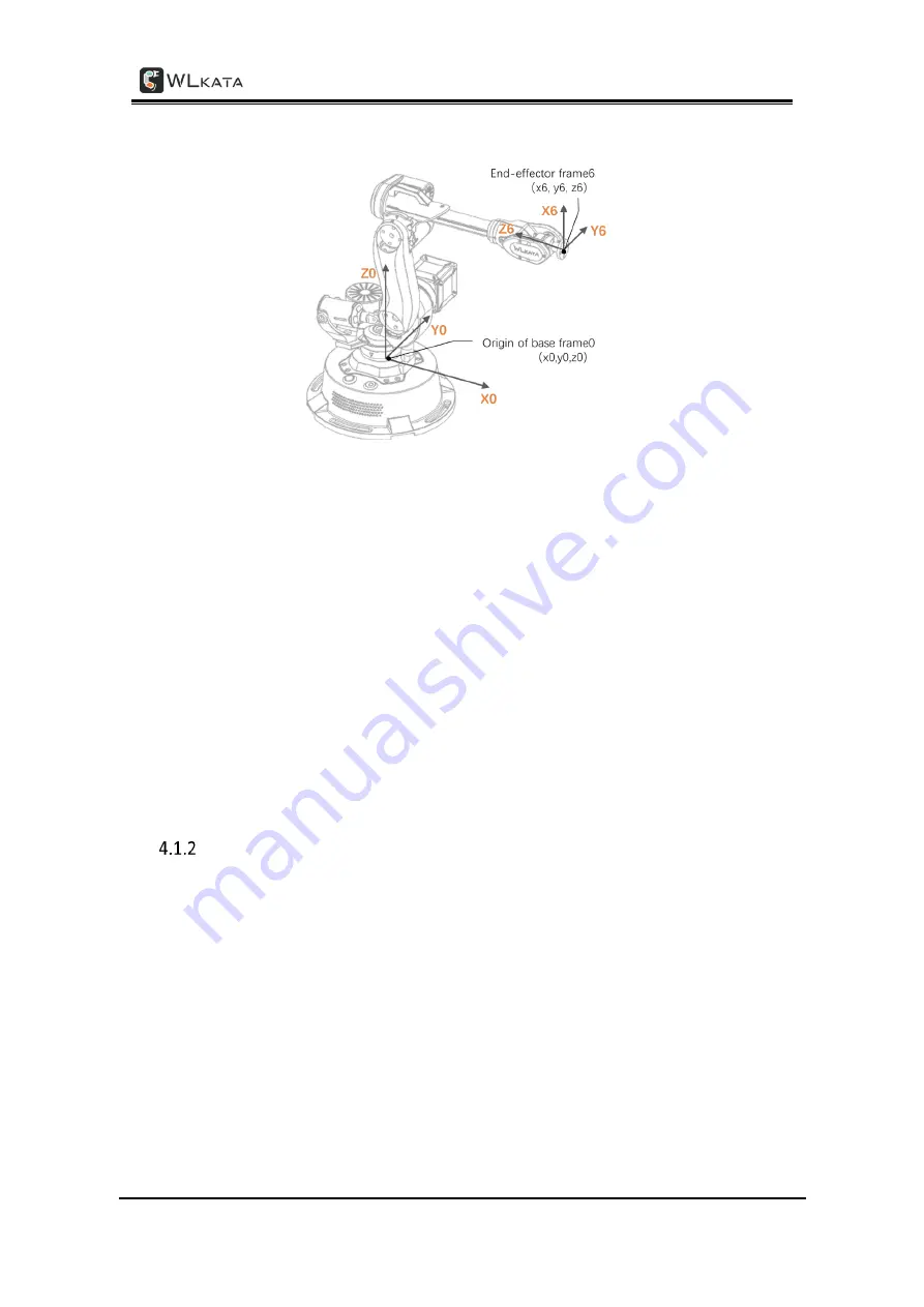
Reference frame (Cartesian space coordinate system) of WLKATA Mirobot
1 Joint coordinate system
: the coordinate system determined by reference to each moving
joint.
•
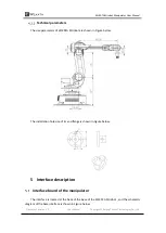
This manipulator has six joints: j1 j2 J3 J4 J5 J6, all of which are rotary joints. The
positive rotation direction of each joint follows the right-hand rule and the thumb
points to the opposite direction of the output shaft of each shaft motor.
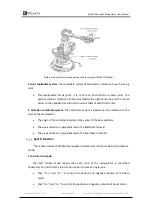
2 Cartesian coordinate system
: The coordinate system is determined by reference to the
base of the manipulator.
•
The origin of the coordinate system is the center of the base platform.
•
The x-axis direction is perpendicular to the fixed base forward.
•
The y-axis direction is perpendicular to the fixed base to the left.
Sports function
The motion modes of Mirobot manipulator include Joint motion mode and Coordinate
mode.
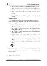
1 Joint motion mode:
the
Joint motion mode means that each joint of the manipulator is controlled
separately. You can click the joint motion button to move a single joint.
•
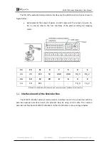
Click "J1 +" and "J1 -" to control the positive and negative rotation of the base
motor.
•
Click "J2 +" and "J2 -" to control the positive and negative rotation of boom motor.

