1-12
Chapter 1: Introduction and Features
November 2007
CPU-NXT2 Board
Identification
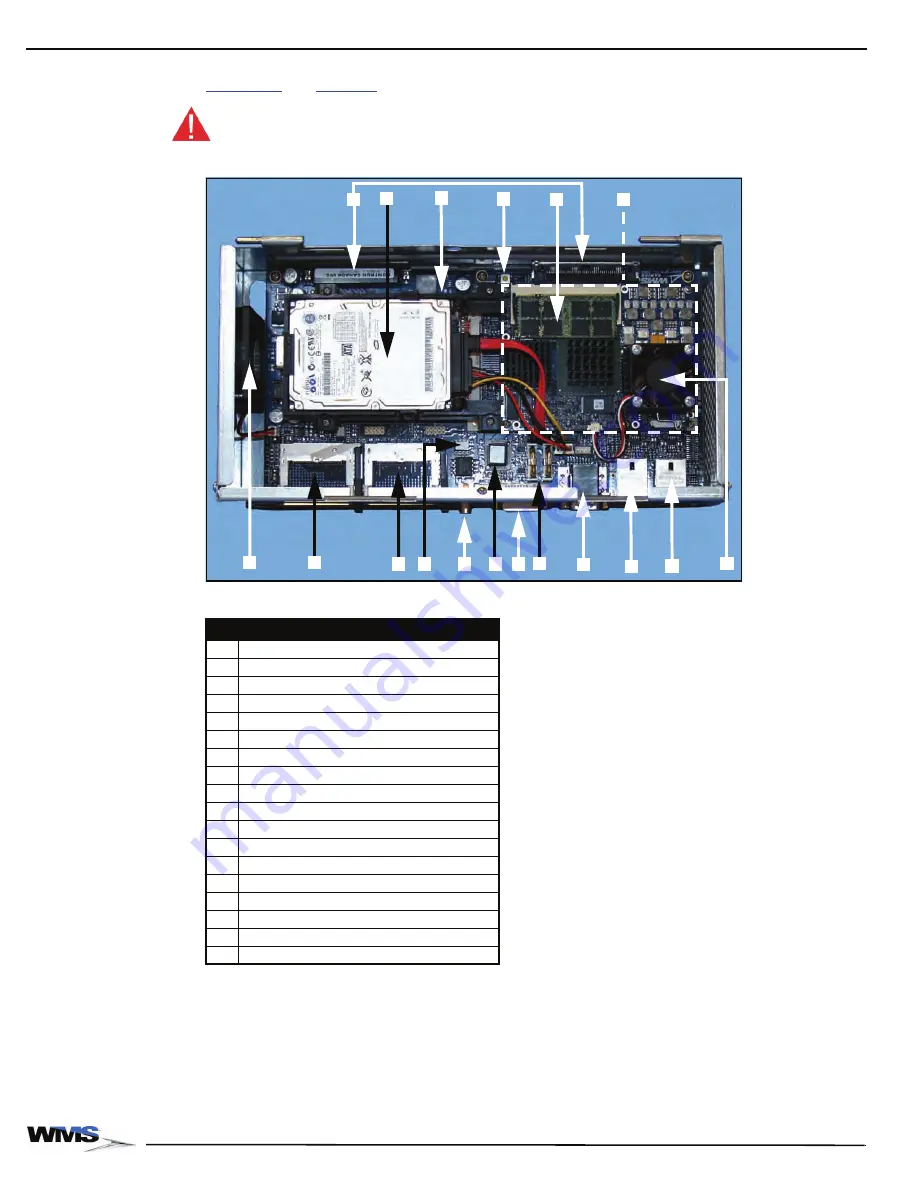
On CPU-NXT2, all components are on the top side of the Printed Circuit Board (PCB). Reference
and
to identify the components on the PCB.
CAUTION: Do not remove the PCB from the enclosure.
Figure 1-17 Layout of CPU-NXT2 PCB.
Table 1-6 Layout of CPU-NXT2.
ID
Connector
A
Blind Mate Connectors
B
Hard Drive
C
PCI Express Video Card (under hard drive)
D
Reset Switch
E
SDRAM Memory Module
F
CPU Module
G
CPU-NXT2 Enclosure Fan
H
CompactFlash Drive (OS software)
I
CompactFlash Drive (game software)
J
Jurisdictional EEPROM (SPI)
K
Digital Audio (SPDIF) Connector
L
BIOS Firmware Hub
M
DVI Video Port
N
Batteries (2) for NVRAM subsystem
O
VGA Video Port/Auxiliary Serial Port
P
10/100/1000 Ethernet/Dual USB Connector
Q
10/100 Ethernet/Dual USB Connector
R
Intel Celeron® M 370, 1.5 GHz Processor
D
B
E
O
I
F
M
H
G
N
A
K
Q
P
R
J
L
C
Summary of Contents for Bluebird Series
Page 2: ......
Page 12: ...4 List of Figures November 2007 ...
Page 16: ...4 About this Guide General Information October 2007 ...
Page 101: ...5 13 Chapter 5 Exploded Views Block Diagram for BBU AC Power Distribution ...
Page 102: ...5 14 Chapter 5 Exploded Views Block Diagram for BBU Bulkhead with CPU NXT ...
Page 103: ...5 15 Chapter 5 Exploded Views Block Diagram for BBU Bulkhead with CPU NXT ...
Page 104: ......


