2-3
Preparation
16-020834-00
3
Pull the Hopper out of the game to gain access to the bolt holes. Carriage bolts are
recommended for mounting the game for security and ease of assembly.
4
Drop four 3/8" x 2" carriage bolts down through the clearance holes and secure the cabinet to
the drop stand with the hex nuts.
NOTE:
Adhere to the following details:
All pilot holes are 0.13" diameter
Large shaded holes are 2.75" diameter
Small shaded holes are 0.50" diameter
CAUTION: WMS requires that all BBU games are mounted to Game Stands using four bolts for
stability and security. Failing to do so may lead to cabinet warping.
Lock Specifications
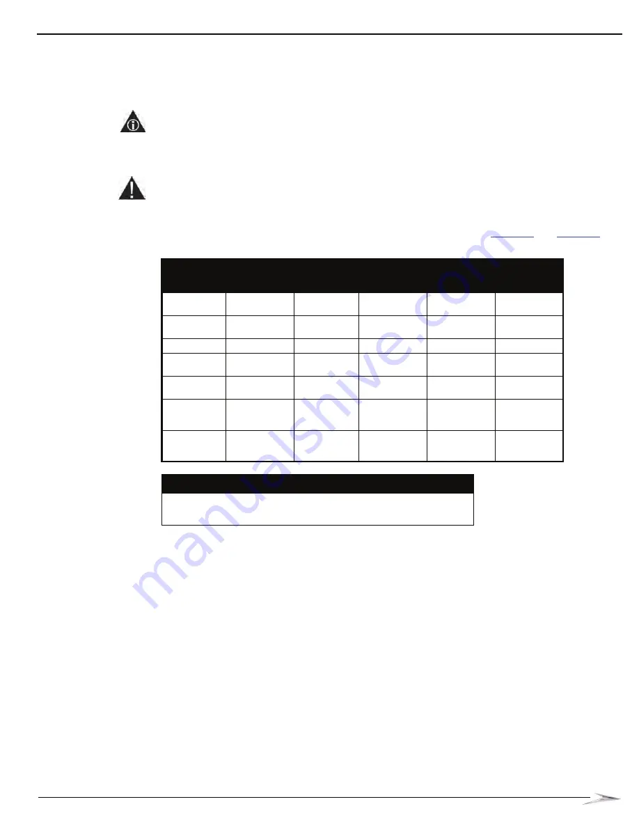
Replace the shipping locks with locks according to the specifications in
and
Table 2-1 Lock Specifications (inches).
Lock Location
Designed
Length
Extended
Length*
Cam
Description
Cam Part No.
Rotation to
Lock (viewed
from key end)
Upper (Main)
Door
5/8"
1/2" inside or
outside
1 1/2" lg. 1/4"
offset
01-001614-04
clockwise
Lower (Belly)
Door
5/8"
1/4" inside,
1/2" outside
1 1/2" lg. 1/4"
offset
01-001614-04
clockwise
CPU Enclosure 5/8"
1/2" outside
Special
01-010849
clockwise
CPU Enclosure
(NJ)
5/8"
1/2" outside
1 1/4" flat
01-12793-08
clockwise
Bill Acceptor
Cassette Door
5/8"
1/2" outside
7/8" flat
01-12793-10
clockwise
Progressive
Meter
Enclosure
5/8"
1/2" inside
15/16" flat
01-12793-07
clockwise
Secondary
LCD Door (Top
Box)
5/8"
1/2" outside
Special
20-9741-G
clockwise
*Conditions:
Extending the lock inside requires a new cam.
Extending the lock outside requires a spacer.
Summary of Contents for Bluebird Series
Page 2: ......
Page 12: ...4 List of Figures November 2007 ...
Page 16: ...4 About this Guide General Information October 2007 ...
Page 101: ...5 13 Chapter 5 Exploded Views Block Diagram for BBU AC Power Distribution ...
Page 102: ...5 14 Chapter 5 Exploded Views Block Diagram for BBU Bulkhead with CPU NXT ...
Page 103: ...5 15 Chapter 5 Exploded Views Block Diagram for BBU Bulkhead with CPU NXT ...
Page 104: ......


