Manual_S5_Airplus_2015_04_20
Page 22 / 68
©
Wodtke GmbH - Tübingen. All Rights and Changes Reserved.Printed 04/2015
Part No. 950 976
8.3.1
"On / Off" (Eigang EIN/AUS) Input -
Display Indicator HE ON / HE OFF
24 V digital input (bridged, protected against po-
larity reversal): for activation / deactivation via an
external, potential-free room thermostat or heating
controller.
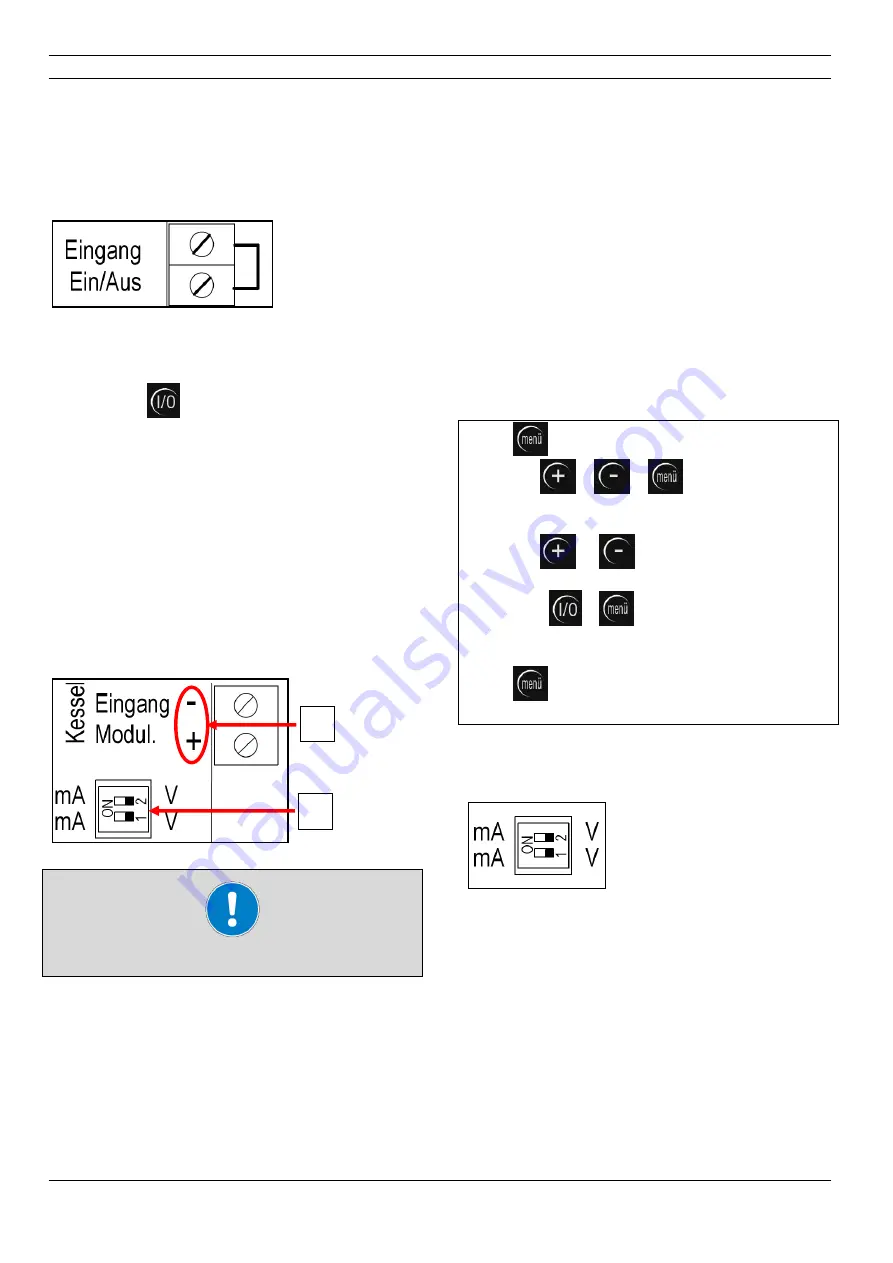
Fig. 34: on/off input
Bridge closed = furnace ON
Bridge open = furnace OFF
Note: Button
on the control board has prior-
ity over the "On/Off" input.
8.3.2
"Modulation"
Input
(Eingang
Modul.)
– Display Indicator HE
Analogue input, 0-10 V or 4-20 mA switchable (not
bridged, note polarity): for modulation of the fur-
nace output via an external modulating room ther-
mostat or heating controller. The "Modulation" in-
put must first be switched active for use. The
"Modulation" input only responds if the furnace is
activated; that is, a combination with the
"ON/OFF" input is required.
Fig. 35: modulation input
1. Attention:
Note polarity
2. DIP switches: V / mA changeover for "Modula-
tion" input
Priorities:
I/O button has first priority, MIN/MAX (external),
ON/OFF (external), R.M (internal) have priority
over modulation.
If the modulation input is switched active, the fur-
nace no longer responds to the RS 485 interface
(BUS is automatically deactivated as soon as
modulation is activated) or to modulation
mode/time switch mode via BB-S5 (TC1).
Notice:
a corresponding controller must be connected to
the modulation input after activation, because oth-
erwise the furnace will run permanently only at the
smallest load.
Activation of the modulation input: Only permitted
for specialist companies! Proceed as follows:
Press
button 1 x
change to menu level 1
Now hold
+
+
buttons simultane-
ously for at least 3 seconds until "S" appears in
the display
change to menu level 2
Now hold
or
buttons pressed until "M
OFF" indicator appears in the display.
Now press
+
buttons simultaneously
until "M ON" indicator appears in the display
the "Modulation" input is now switched active.
Press
button for at least 3 seconds
return
to operating level
Switch over modulation input from 0-10 V to 4-20
mA:
Fig. 36: modulation DIP switches
0-10 V = both DIP switches to V to the
right;
4-20 mA = both DIP switches to mA to the
left
1
2


