Manual_S5_Airplus_2015_04_20
Page 24 / 68
©
Wodtke GmbH - Tübingen. All Rights and Changes Reserved.Printed 04/2015
Part No. 950 976
8.3.4
"Min/Max" (Eingang Min/Max) Input
- Display Indicator HM
24 V digital input (bridged, protected against po-
larity reversal): for switching the furnace output
between smallest load and the output preset on
the control board via an external, potential-free
room thermostat or heating controller. The
"Min/Max" input has priority over the "Modulation"
input and the output preset on the control board.
Bridge closed = furnace runs at output pre-
set on control board
Bridge open = furnace runs at minimum
(smallest load) HM
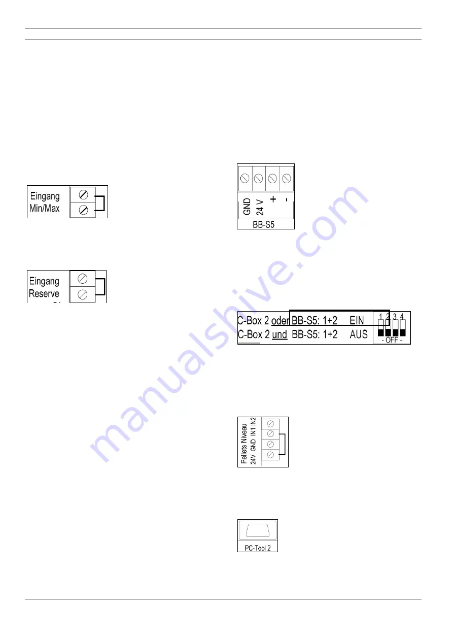
Fig. 39: min/max input
8.3.5
"Reserve" Input (Eingang Reserve)
- Display Indicator RE Er1
Fig. 40: reserve input
24 V digital input (bridged, protected against po-
larity reversal): for feedback (monitoring function)
from external devices to the furnace.
Bridge closed = everything ok, furnace re-
sponds normally
Bridge open = external fault, furnace does
not operate or goes to fault shutdown
Every time the furnace is started (manual start, au-
tomatic start or restart after power failure), it is
queried after 15 seconds whether the potential-
free bridge on the "Reserve" input is closed. The
furnace only operates if the "Reserve" input is
closed no later than after 15 seconds. It is then
permanently monitored during operation whether
the bridge is closed.
If the bridge is opened during operation, a fault
shutdown occurs ("RE Er1" indicator blinking in al-
ternation with "G OFF" or "Stand-By-Dot") and
heating operation is not possible. A reset of the
"RE Er1" error message and a restart as a result
is only possible if the external error is resolved and
the "Reserve input" is bridged (closed) again.
Application examples:
Interlocking furnace with ventilation system / fume
hood (furnace off if ventilation on)
Flue gas damper for flue gas / inlet damper for
combustion air (wodtke AK1)
8.3.6
"BB-S5" Input - Connection of
wodtke Touch-Control TC1 (Acces-
sory)
Fig. 41: Touch Control input
See the separate instructions for the wodtke
Touch Control TC1. The TC1 can additionally be
connected to the control board or to the furnace
alone. When connecting the TC1 to the main
board of the furnace, set the DIP switches 1+2 to
"ON."
Fig. 42: Touch Control DIP switches
The furnace automatically recognises the TC1
and then responds to its commands.
8.3.7
"Pellets Level" (Pellets Niveau) In-
put (Inactive)
Fig. 43: pellets level input
Inactive / cannot be used
8.3.8
"PC- Tool 2" Input
Fig. 44: PC Tool 2 Input
RS 232 interface with 9-pin SUB-D coupling: for
connection of the wodtke PC-Tool 2 diagnostic
system (only for specialist companies).


