


GMF-S01 Operation manual
Page 13 of 31
B0836
4.2 Drive
4.2.1 Hydraulic motor
The hydraulic motor of the pump unit is operated by means of a pressurised hydraulic fluid.
This fluid is supplied via a fixed piping. Such piping may be laid by qualified professionals
only.
The hydraulic fluid is fed and discharged through two G 3/8 connection holes. The direction
of flow can be selected freely.
4.2.2 Electric motor (option)
By using the attaching parts (752.528-70) a three-phase current motor, with flange-FT85
DIN EN 50347 (C105 DIN 42948) can be mounted on the side of the pump case. Connec-
ting of the electric motor may be laid by qualified professionals only.
4.3 Functioning
The hydraulic motor is used to drive the pump shaft through a worm gear. Together with
this pump shaft, a pressure ring, which the pump elements are hooked into, is rotating
eccentrically. Due to the eccentricity of the pressure ring in relation to the pump shaft, every
delivery piston is forced with every rotation of the pump shaft to perform one steady delivery
and suction stroke each. The functioning of the pump elements will be described later on.
The pump shaft is connected with a stirring unit that pushes the lubricant to the suction holes
of the pump elements and crushes the air bubbles.
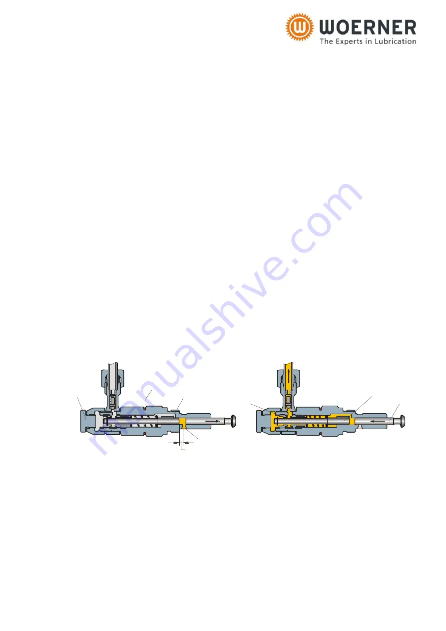
4.4 Pump elements
4
3
R
7
Delivery volumen
1
2
6
The suction stroke is performed by delivery piston
1
and control piston
2
. In this action,
delivery piston
1
is actuated by the eccentric shaft, and control piston
2
is actuated by the
spring. The control piston closes delivery hole
3
and is retained in a certain position de-
pending on the delivery volume set. The delivery piston continues to move. As a result, a
vacuum is built up in the metering chamber. After opening of suction hole
4
by the delivery
piston, lubricant will be drawn from the reservoir.
In delivery stroke, delivery piston
1
moves to the left. In this motion, suction hole
4
will be
closed and control piston
2
displaced by the lubricant being available in between the delivery
piston and the control piston until it releases delivery hole
3
and the lubricant is delivered by
the delivery piston to the outlet.
Pump element
8
is marked by a red ring R.


