Data sheet
P0688 EN
Page 6 of 7
Data sheet
P0688 EN
Page 5 of 7
I
II
III
1
2
3
4
5
6
Left-side
bypassline
Right-side
line
bypass
Mainline
Fig. 1
II
II
1
2
3
4
5
6
Fig. 3
I
1
2
3
4
5
6
Fig. 2
III
1
2
3
4
5
6
Fig. 4
Monitoring of
progressive distributors
As for instance due to soiling, the flow
through a lubricant point line may be
prevented. This will cause a piston to get
blocked. By virtue of the forced control as
depicted in figures 1 up to 4, the other
pistons will be stopped as well.
Due to this configuration, the proportioning
at all outlets of the distributor can be
monitored by means of a sensor at one
piston only.
Mounting note:
The pistons are provided with an extremely
small fitting clearance. Therefore, the pis-
tons, after the dismantling of a distributor,
must never be interchanged.
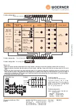
Distinctive letters
ouble bridge without
check valve
riple bridge without
check valve
utlet at the bridge
without check valve
opposing outlets
separated
opposing outlets
connected
open outlet
ock screw
:
B = D
P = T
A = O
Z =
K =
0 =
V = L
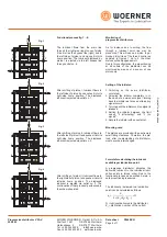
Setting of the initiator:
1. Switching on the pump (distributor
circulates).
2. Screwing the initiator completely in. In
the case of a permanent signal, turning
back the initiator as far as an alternating
signal occurs.
3. Turning back the initiator until no signal is
released.
4. Setting the initiator between the limit
values
2 (alternating)
and
3 (no
signal)
5. Secure the initiator with a counter nut.
"
"
"
".
Progressive distributor VPA-C
205.000
Progressive distributor VPA-C
205.000
Combination of outlets,
doubling the proportioning volume at an outlet:
Connect opposing outlets by removing the "Z" screw.
Close any of the outlets by means of a screwed sealing plug
Without removal of the "Z" screw, no outlet must be locked.
.
Z
2 adjacent outlets are combined into
one outlet by means of a double
bridge.
Add-on elements and combination of outlets:
5 outlets are combined into one outlet
by means of a triple bridge, a double
bridge, and removal of the "Z" screws.
Open outlets
2 opposing outlets are combined by
removing the "Z" screws.
Side A (R)
Centre
Side B (L)
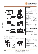
Accessories
Pipe screw fittings
:
DIN 2353 and lock screw:
.
(
)
please state purchase-no.
Only in conjunction with progressive distributor. For spare parts see spare part list E0117
Bridges:
(please state purchase-no.)
double without
outlet (B-B)
triple without
outlet (P-P-P)
double with
outlet (B-A)
triple with
outlet (P-P-A)
752.205-90
752.205-91
752.205-92
752.205-93
Bridges
double without
outlet (B-B)
triple without
outlet (P-P-P)
double with
outlet (B-A)
triple with
outlet (P-P-A)
752.205-94
752.205-95
752.205-96
752.205-97
Bridges
(
"S")
location of the mid fastening screw
For mid fastening screw "S" position
–
–
752.205-98
752.205-99
–
–
752.205-A0
752.205-A1
without
with
Check valve
at the outlet
1)
Outlet at max ø10
Connection
thread
G 1/4
951.100-51
951.100-12
951.100-14
951.100-17
6
8
10
12
Pipe screw fitting with pipe outer diameterø
1)
206.674-65
Check valve with pipe outer diameterø
501.152-65
501.151-65
501.153-65
6
8
10
Lock screw
"V"
Functional process fig. 1 ... 4:
The lubricant flows from the main line
through the right-side ring groove of piston
III as well as the bypass line (right) and to
the left side of piston I and moves it into its
home position. The lubricant displaced by
piston I is ejected via the left bypass line
through outlet no. 6
After shifting of piston I, lubricant flows to
the left side of piston II and pushes it into its
right-side home position. The displaced
lubricant is ejected via outlet no. 1
After shifting of piston II, lubricant flows to
the left side of piston III and pushes it into its
right-side home position. The displaced
lubricant is ejected via outlet no. 2
After shifting of piston III, lubricant flows to
the right side of piston I and pushes it into its
left-side home position. The displaced
lubricant is ejected via outlet no. 3. The
continuation of that process is evidenced in
the scheme depicted
.
.
.
.
Formula for calculating the lubricant
available per lubrication point:
A progressive distributor allocates the
delivered lubricant to the individual lubri-
cation points in forced order. Due to the
functional process as described herein, a
safe proportioning is ensured
The lubricant
delivered to a lubrication
point i can be calculated as follows
lubricant delivered to the distributor
.
Q =
,
K =
i
i
distinctive number of the outlet
q
i
q =
Q
i
¾¾¾¾¾¾¾¾ *
K
i
2 (K +K +K ...)
*
1
2
3
-Subjecttomodifications-
-Subjecttomodifications-
EUGEN WOERNER
GmbH & Co. KG
Postfach 1661
DE-97866 Wertheim
Hafenstrasse 2
DE-97877 Wertheim
Tel. +49 9342 803-0
Fax. +49 9342 803-202
www.woerner.de
info@woerner.de
EUGEN WOERNER
GmbH & Co. KG
Postfach 1661
DE-97866 Wertheim
Hafenstrasse 2
DE-97877 Wertheim
Tel. +49 9342 803-0
Fax. +49 9342 803-202
www.woerner.de
info@woerner.de


