Wogaard Coolant Saver
TM
Manual
Version 1.2-Eng
Page
12
of
19
6.
The 12 mm PU hose is inserted at the end of the venturi-unit pointing towards the ground.
The hose should be cut to length with a utility knife, so the end of the hose is approx an
inch above highest possible water-level.
Caution:
Avoid bending the 12mm hose. Please ensure that the hose is mounted in a way
that prevents it from shifting position, as a result of changes in flow. You should drill a 12.5
- 14 mm hole in the top plate of the coolant reservoir to accommodate the 12mm PU hose.
If you feel uncomfortable doing this, you can alternatively fix the hose in an appropriate
manner using regular cable ties. THE HOSE MUST NOT TWIST OR BEND SHARPLY! If the
liquid cannot flow through the hose, it will come out of the vacuum cup!
7.
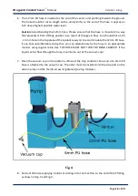
Place the vacuum cup on the bottom surface of the chip container. One end of a 6mm PU
hose is attached to the vacuum cup. The other must be inserted into the side port on the
venturi-unity and the thumb-screw is tightened (see fig. 4 below).
Fig. 4
8.
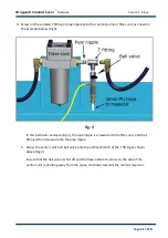
Connect the hose supplying coolant or cutting oil to the machine, to the end of the T fitting
as shown in Fig. 3 and Fig. 4.


