background image

821042: RMT-170e Series User Guide
© 2011 Wohler Technologies, Inc. All rights reserved.

ii


© 2011 Wohler Technologies, Inc.. All rights reserved.

This publication is protected by federal copyright law. No part of this publication may be 

copied or distributed, stored in a retrieval system, or translated into any human or computer 

language in any form or by any means electronic, mechanical, manual, magnetic, or otherwise, 

or disclosed to third parties without the express written permission of Wohler Technologies.

Reproduction

Licensed users and authorized distributors of Wohler Technologies, Inc. products may copy 

this document for use with Wohler Technologies., Inc. products provided that the copyright 

notice above is included in all reproductions.

Customer Support

Wohler Technologies, Inc.

31055 Huntwood Avenue

Hayward, CA 94544

www.wohler.com

Phone: 510-870-0810

FAX: 510-870-0811

US Toll Free: 1-888-596-4537

(1-888-5-WOHLER)

Web: www.wohler.com

Sales: sales@wohler.com

Support: support@wohler.com

Disclaimers

Even though Wohler Technologies, Inc. has tested its equipment and software, and reviewed 

the documentation, Wohler Technologies, Inc makes no warranty or representation, either 

express or implied, with respect to software, documentation, their quality, performance, 

merchantability, or fitness for a particular purpose.

In no event will Wohler Technologies, Inc. be liable for direct, indirect, special, incidental, or 

consequential damages resulting from any defect in the hardware, software, or its 

documentation, even if advised of the possibility of such damages.

Some states do not allow the exclusion or limitation for incidental or consequential damages, so 

the above exclusion or limitation may not apply to you

.

Printing

This document is intended to be printed on a duplex printer, such that the copy appears on 

both sides of each page. This ensures that all new chapters start on a right-facing page.

This document looks best when printed on a color printer since some images may be indistinct 

when printed on a black and white printer.

Other Technologies and Products

Dolby is a registered trademark of Dolby Laboratories, Inc.

Microsoft Windows, and Internet Explorer are registered trademarks of Microsoft Corporation.

Last Update

June 16, 2011

Summary of Contents for 821042

Page 1: ...RMT 170e HD Series RMT 170e HD RMT 170e SD 17 Inch High Definition Video Monitors User Guide Part Number 821042 Revision A...

Page 2: ...Technologies Inc has tested its equipment and software and reviewed the documentation Wohler Technologies Inc makes no warranty or representation either express or implied with respect to software doc...

Page 3: ...features including IMD tally time code closed captioning format display and area title safe The RM 170e Series also provides a host of audio tools including level metering and built in speaker monito...

Page 4: ...qual width 8 Protect the power cord from being walked on or pinched particularly at plug s source on the equipment and at the socket 9 Use only the attachments accessories specified by the manufacture...

Page 5: ...warranty card and Either A table stand and two M5 x 5 mm screws or Two rack mount ears and M4 X 13 mm screws Optional A battery mount and four M3 x 12 mm screws 1 When installing a mount option use a...

Page 6: ...RMT 170e HD Series monitor above the power connector FCC Compliance This equipment has been tested and found to comply with the limits for a Class A digital device pursuant to part 15 of the FCC Rule...

Page 7: ...nd 2 are also available for use with internal speakers The GPI style tri color tally provides red green amber indication using an industry standard RJ 45 connection 1366 x 768 screen resolution 16 9 n...

Page 8: ...ck mount Digital Inputs 2 SD SDI with loop through 2 HD SD SDI with loop through Common Inputs 1 Component Video CVSB 1 Configurable Video Y C YPbPr Composite 1 Configurable HDMI VGA DVI on DVI I 4 Au...

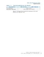
Page 9: ...HD Series User Guide Specifications Figures 1 3 through below illustrate the dimensions of the unit s features in four different views Viewing Angles 178 H x 178 V Operating Temperature 32 F to 122 F...

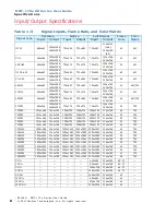
Page 10: ...720x576 1366x768 1024x768 50 709 720P24 1216x684 1366x768 1280x720 1280x720 1280x720 1366x768 48 709 720P25 1216x684 1366x768 1280x720 1280x720 1280x720 1366x768 50 709 720P30 1216x684 1366x768 1280x7...

Page 11: ...C YPbPr HDMI DVI VGA NTSC Yes Yes PAL Yes Yes SECAM Yes Yes NTCS 4 43 Yes Yes PAL M Yes Yes 4080I60 Yes Yes Yes 576I50 Yes Yes Yes 480P60 Yes Yes 576P50 Yes Yes 720P24 HDa a All formats marked HD are...

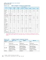
Page 12: ...s Yes Mono Yes Yes Yes Yes Yes Yes H V Delay Yes Yes Dot Phase Yes H Position Yes V Position Yes Audio Ext Ext Ext Ext Ebd Ext Ebd Ext Ebd Time Code Yes Yes UMD Yes Yes Yes Yes Yes Yes Audio Meter Yes...

Page 13: ...R BT656 270Mbps 525 625 SD component 1485 Mbps HD Impedance 75 Return Loss 18dB 5 MHz to 540 MHz Equalization Automatic equalizing to 30dB 270 Mb s Table 1 9 SDI Video Output Specifications Parameter...

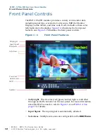
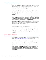
Page 14: ...e the display Figure 1 1 illustrates the front panel features and Figure 1 2 illustrates the front panel controls Figure 1 1 Front Panel Features Tally Light This tri color red green amber light is co...

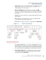
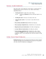
Page 15: ...is configurable in the OSD Menu Figure 1 2 Front Panel Controls Button Indicators Power Button Indicator As an indicator the Power button glows green when power is on switch is on the back panel and...

Page 16: ...f the OSD Menu Aspect Button Indicator This indicator glows green when a non default aspect ratio has been selected for this signal As a control this button toggles between 4 3 and 16 9 F1 through F6...

Page 17: ...Phase Rotary Knob Indicator Modifies the sharpness Chroma Rotary Knob Indicator Modifies the color saturation Brightness Rotary Knob Indicator Modifies the brightness Contrast Rotary Knob Indicator Mo...

Page 18: ...1 3 on page 16 illustrates the rear panel connectors Figure 1 3 RMT 170e HD Rear Panel Tally Light Control GPI RJ45 This connect provides control to the front panel tri color tally light and other rem...

Page 19: ...signal or luminance Y signal of Y C or YPrPb Line 2 C Pb Input jack for Chroma C signal of Y C or Pb Blue component of YPrPb Line 2 Pr Input jack for Pr Red component of YPrPb Config I O on DB 9 Remo...

Page 20: ...dio Output Output jacks for the analog audio signal Power Switch Toggling the power switch powers the monitor on or off DC Power Connector Connect DC power to this four pin female connector 12V 6A See...

Page 21: ...FIG G CONTROL 3 Press the Enter button to enter the parameter selections in the chosen sub menu 4 Use the Up or Down buttons to cycle through the sub menu selections 5 When the desired option is highl...

Page 22: ...y only Non selectable The values vary depending on input signal type and configuration settings COLOR TEMP COMPO LEVEL NTSC SETUP SCAN MODE AUTO STANDBY MODEL COLOR TEMPa COLOR TEMP D65 Selects the co...

Page 23: ...tio according to the display aspect Aspect 16 9 Off 4 3 Vertical 15 9 Vertical 14 9 Vertical 13 9 Vertical 1 85 1 Horizontal 2 35 1 Horizontal Aspect 4 3 Off 16 9 CENTER MARKER ON ON enabled or OFF di...

Page 24: ...e line for area marker edge only HALF 50 Back ground brightness BLACK Black VIDEO CONFIG APERTURE 20 0 to 100 AUDIO CONFIG SOURCE TYPE EXT Used to select the audio source type where EXT Analog audio S...

Page 25: ...where If SOURCE TYPE NONE then OFF If SOURCE TYPE AUD then AUD 1L AUD 1R AUD 2L and AUD 2R If SOURCE TYPE EBD and the input signal is SDI then EBD CH1 through EBD CH16 If SOURCE TYPE EBD and the input...

Page 26: ...f SOURCE TYPE EBD and the input signal is SDI then EBD 1through EBD 16 If SOURCE TYPE EBD and the input signal is HDMI then EBD 1 through EBD 8 METER 2 METER 3 METER 4 METER 5 METER 6 METER 7 METER 8...

Page 27: ...itor keeps power on regardless of the input signal status LANGUAGE ENGLISH ENGLISH CHINESE In Chinese COMPO LEVEL SMPTE Only for 480i60 component input where SMPTE 100 0 100 0 signal BETA0 100 0 75 0...

Page 28: ...P LEFT Determines the location on the monitor where the waveform displays BOT LEFT The waveform will cover the original information on the screen BOT RIGHT The waveform will cover the original informa...

Page 29: ...where MARKER Turns all markers ON or OFF AUDIO METER Turns all audio meter displays ON or OFF WAVE FORM Turns display ON or OFF H V DELAY Toggles the values OFF H V and H V AUTO SETUP Press to auto ad...

Page 30: ...CAN OVER SCAN NATIVE ASPECT 4 3 ASPECT 16 9 or MARKER ENABLE GPI2 TALLY G GPI3 SDI 1 GPI4 SDI 2 GPI5 LINE 1 GPI6 LINE 2 CONTROL KEY INHIBIT OFF Inhibits the use of all buttons except Power Menu and Vo...

Page 31: ...face GPI Interface LED Tally Programming 4 to 8 for De embedded 2 to 4 for Analog Audio In 2 SDI Input Select Video Source Select Audio Source Select SD SDI Input 2 SD SDI Select Out Line 1 Composite...

Page 32: ...Interface LED Tally Programming 4 8 for De embedded 2 4 for Analog Audio Channel Select SDI Input Select Video Source Select Audio Source Select HD SD SDI Input 2 HD SD SDI Select Out Line 1 Composit...

Reviews: