background image


Page 

31


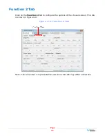
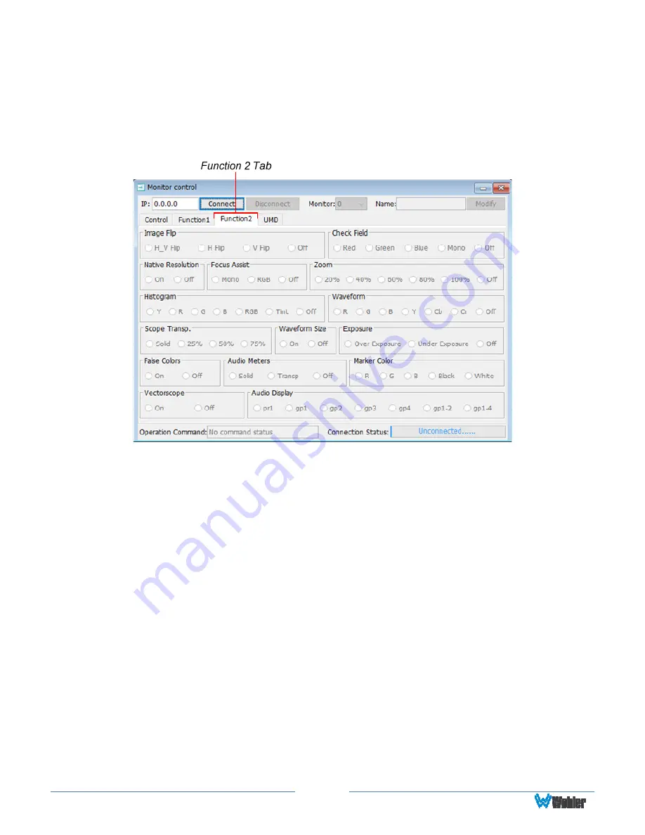
Function 2 Tab 

Click on the 

Function 2

 tab to configure the options of the chosen screen. This tab 

is shown in Figure 4-8: 

Figure 4–8: Function 2 Tab 


Note: The tab shown is representative and the actual tab may differ somewhat. 


Summary of Contents for RM-3270W-3G2

Page 1: ...RM 3270W 3G2 3RU 2 Screen 7 Dual 3G HD SD SDI Input Audio Video Monitor User Guide Part Number 821825 Revision A...

Page 2: ...s equipment and software and reviewed the documentation Wohler Technologies Inc makes no warranty or representation either express or implied with respect to software documentation their quality perfo...

Page 3: ...erference 6 Power 6 Compliance 6 FCC 6 ICES 003 7 CHAPTER 2 Local Operation 8 Front Panel 8 On Screen Display Features 9 Rear Panel 11 Rear Panel Connectors 13 Using the Volume Control and the OSD Men...

Page 4: ...en markers waveform vector and histogram displays can be enabled on this full featured monitor Focus Assist mode can be engaged to assist with camera adjustments Stereo speakers as well as a headphone...

Page 5: ...s Mounting The unit is designed for a standard 19 rack Install it at ear eye level for best high frequency response and visual observation of the display screens Please adhere to the following clearan...

Page 6: ...nough such reflections can result in corruption of the digital data stream As with any audio equipment maximum immunity from electrical interference requires the use of shielded cable however satisfac...

Page 7: ...may cause harmful interference to radio communications Operation of this equipment in a residential area is likely to cause harmful interference in which case the user will be required to correct the...

Page 8: ...in this chapter 4 Headphone Jack Monitor the assigned left right stereo audio channels with stereo headphones from this mini stereo connector Control the volume of the headphones using the Left and R...

Page 9: ...ENU is not displayed pressing this button initiates the F2 function per its function key menu setting 11 F3 Pressing this button initiates the F3 function per its function key menu setting 12 F4 Press...

Page 10: ...t whether to display it in the DISPLAY menu 4 Center Marker Cross hairs are displayed in the center of the screen marking the center of the image You can set whether to display it in the DISPLAY menu...

Page 11: ...connector provides a re shaped and re clocked duplicate of the 3G SDI In 2 signal This connection is compliant with SMPTE 424M SMPTE 259M SMPTE292M ITU R BT601 Important The monitor and power adapter...

Page 12: ...ply plugs into this coax connector 12 Chassis Ground This terminal may be used if needed to connect a grounding wire to the chassis 13 Ethernet The 10 100M Ethernet connector is used to connect with a...

Page 13: ...are also silkscreened on the rear panel of the unit for your convenience Table 2 1 Tally Connections Pin Tally Terminal Name 1 CH1 R 2 CH2 R 3 CH3 R 4 NC 5 GND 6 CH1 G 7 CH2 G 8 CH3 G Figure 2 4 Tall...

Page 14: ...as the adjustment is made to provide a graphical and numeric indication of the level The range is 0 to 100 The Volume Setting Indicator appears as shown in Figure 2 6 Figure 2 6 Volume Setting Indica...

Page 15: ...enu button to accept your parameter change 7 Press the Menu button to back out of any submenu and finally to remove the OSD Menus from the screen OSD Menus The following tables describe the informatio...

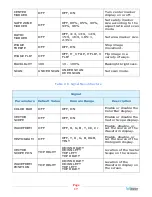
Page 16: ...isplay Parameters Default Value Domain Range Description ASPECT RATIO PANORAMA PANORAMA AUTO 4 3 16 9 ZOOM 1 ZOOM 2 JUST SCAN Turn all markers on or off ANAMORPHIC OFF OFF 1 3X 2 0X 2 0X MAG Adjust im...

Page 17: ...VER SCAN Set scan mode Table 2 6 Signal Menu Structure Signal Parameters Default Value Domain Range Description COLOR BAR OFF OFF ON Enable or disable the Color Bar display VECTOR SCOPE OFF OFF ON Ena...

Page 18: ...REEN Set the screen color displayed when there is no video signal CHECK FIELD OFF OFF MONO RED GREEN BLUE Enable or disable the display of check screen colors NATIVE RESOLUTION OFF OFF ON FOCUS ASSIST...

Page 19: ...D IMD BLACK OFF RED GREEN ORANGE BLACK Add a colored box behind the IMD text To enter the characters for the MODIFY IMD setting navigate to the setting and press Right Press Up or Down repeatedly to l...

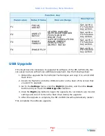
Page 20: ...Menus MENU DWELL TIME 30 SEC OFF 10 SEC 20 SEC 30 SEC Adjust the timer for the OSD Menus to disappear SIGNAL INFO 5 SEC 2 SEC 5 SEC 10 SEC ON Adjust the amount of time that the Signal Display remains...

Page 21: ...ade the software of the RM 3270W 3G this can easily be done without any additional equipment Use the following steps 1 Obtain the upgrade file from Wohler Technologies and copy it to a mini USB flash...

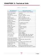
Page 22: ...V Aspect ratio 16 9 Display Area mm 153 6 H x 90 0 V Viewing Angle 178 H x 178 V Color Depth 16 7M colors Contrast Ratio 800 1 Brightness 400 cd m2 typical Response Time 30 ms typical CVBS PAL NTSC SD...

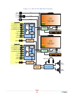
Page 23: ...rade 2 Screen 2 Controls Screen 1 I O 3G HD SD SDI 1 In 3G HD SD SDI 2 In CVBS In Audio In 3G HD SD SDI 1 Out 3G HD SD SDI 2 Out CVBS Out HDMI In HDMI Out L R Screen 1 Audio Select De Embed A D Conv C...

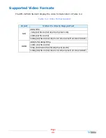
Page 24: ...3 2 Video Format Support Input Video Formats Supported 480i 576i 720p 60 59 94 50 30 29 25 24 23 98 1080i 60 59 94 50 SDI 1080p 60 59 94 50 30 29 97 25 24 24sF 23 98 23 98sF 480i 576i 480p 576p 1080i...

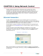
Page 25: ...he address as shown on the display is shown at 255 255 255 255 It will be automatically configured as it connects Use the Ethernet jack on the back panel for the network connection The first step in r...

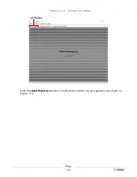
Page 26: ...Page 26 Figure 4 2 Control Interface Click the Add Monitors button The Monitor Control screen appears as shown in Figure 4 3...

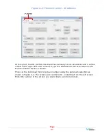
Page 27: ...in the upper left of its screens Type this address into the IP location on the Monitor Control screen in the PC Then set the individual monitor screen number using the pull down selection as shown in...

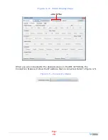
Page 28: ...Figure 4 4 Video Display Page When you are connected to the desired screen on the RM 3270W 3G the Connection Status will show the IP address that is connected Refer to Figure 4 5 Figure 4 5 Connection...

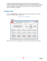
Page 29: ...r tabs The screens are self explanatory and simple to operate The descriptions of the options on the screens correspond to those in the tables in Chapter 2 Control Tab Click on the Control tab to conf...

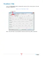
Page 30: ...Click on the Function 1 tab to configure the options of the chosen screen This tab is shown in Figure 4 7 Figure 4 7 Function 1 Tab Function 1 Tab Note The tab shown is representative and the actual t...

Page 31: ...n 2 Tab Click on the Function 2 tab to configure the options of the chosen screen This tab is shown in Figure 4 8 Figure 4 8 Function 2 Tab Note The tab shown is representative and the actual tab may...

Page 32: ...in Figure 4 9 Figure 4 9 UMD Tab UMD Tab Note The tab shown is representative and the actual tab may differ somewhat When you are finished setting up the chosen screen you may use the Monitor pull dow...

Reviews: