8
© 2006 PANORAMAdtv ALL rights reserved
RM-3358W
User Manual P/N
821575
Rev-
C
5
1
2
3
4
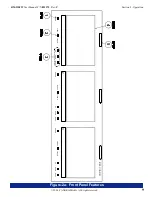
Please refer to
Figure-2a
on the following page to familiarize yourself with the front panel features of the
RM-3358W
unit. The
following sections describe these functions and are referenced, by number, to
Figure-2a
.
Section 2: Operation
Front Panel Features
Power Button (1-3)
These button switches (
1
-
3
) are used to cycle each individual LCD display
ON
/
OFF
.
A/B Source Select Switch (1-3)
In a standard configuration, this switch selects between the
primary
CVBS
(
VIDEO A
) and
secondary
CVBS
(
VIDEO B
)
video source inputs for the associated
I/O Section
.
If an optional
SDI Input Module
(
RMSDI-1
or
RMSDI-2
) is installed in an
I/O Section
, the associated switch selects
between the primary
CVBS Input
source (
VIDEO A
) and the
installed
SDI Input
video source (
VIDEO B
).
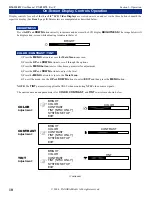
LCD Video On-Screen Display Controls (1-3)
Each LCD video display can be adjusted separately using the on-screen display controls. See page
10
for a description
how to adjust these parameters. The following parameters may be adjusted:
• Brightness
- adjust for desired screen brightness.
• Contrast
- adjust for desired image scene, dark-to-bright contrast.
• Color (Saturation)
- adjust for desired amount of image color saturation.
• Tint (Hue)
- adjust for desired image color hue (NTSC only).
• Dimmer Level
-
1
to
8.
• Power Savings
-
ON
/
OFF
(turns monitor off if no video signal after 6 seconds, returns power at signal).
• Frequency Subcarrier
- select
3.58 MHz
or
4.43 MHz
for frquency subcarrier.
• Horizontal Normal
- reverses image horizontally.
• Vertical Normal
- reverses image vertically.
• Mode
-
NORMAL
(original aspect ratio),
ZOOM1
(arbitrary zoom in), or
FIT
(stretches image to fit screen).
LCD Video Display (1-3)
View input video sources here. Select one of two source inputs for each display by setting the
A/B Source Select Switch
(
Item 2
) to the desired input (
VIDEO A
or
VIDEO B
). A number of screen image parameters are adjustable using the on-
screen display controls (see
Item 3
).
Note that when no source signal is being input to a powered display, a "
NO SIGNAL
" message will show in the display
screen until a source signal is applied.
Tally Indication LED (1-3)
This tri-color LED can glow RED, GREEN, or YELLOW to indicate tally status associated with the signal displayed.
Refer to pages
16
and
17
for tally connection details.
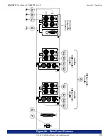
An optional audio indication module (
AIM-1
) may be installed into the
Tally Control Connector
on the rear panel (
Item
E
, page
12
), which allows these LEDs to act as audio indicator lights. Please contact
PANORAMAdtv
for more information
about this optional feature.


