Page
10
Audio level meter
displays, for up to sixteen channels, can be displayed on either
the left or the right of the display. They can show VU, PPM (PK) or both with
assignable -20db or -18db reference levels.
Waveform
(Y or Line),
Vectorscope
, or
Histogram
can be shown in various
positions almost anywhere on the screen.
The de-embedded
Timecode
from the HD/SD-SDI source displays on the lower
part of the screen.
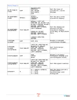
Figure 2-2: Display Features
1.
Input Status
: Displays the detected input and video parameters of the
signal: vertical active line count, (i)nterlaced or (p)rogressive, and
field/frame rate in Hz. This display is controlled be a setting in the Config
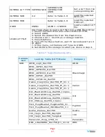
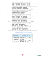
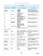
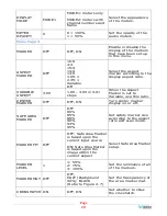
Menu. Refer to Table 2-9.
2.
Area Marker
: Used to mark an alternate aspect ratio area of the image. You
can set whether to display it, the brightness, and the matte mode in the
Config Menu. Refer to Table 2-9.
3.
Safety Marker
:
This is used to mark a percentage area, inside of the image,
safe for titles to be located. You can set whether to display it, as well as its
display mode, in the Config Menu. Refer to Table 2-9.
4.
Center marker
:
Cross hairs
are
displayed in the center of the screen,
marking the center of the image. You can set whether to display them in the
Config Menu. Refer to Table 2-9.
5.
IMD
:
The IMD Menu provides settings to customize the IMD (In Monitor
Display) text area to show a static line of characters, numbers, and certain
symbols or to receive dynamic messages to be displayed. Refer to Table 2-
10.
6.
Audio Level Meters
:
Levels for the audio channels are displayed on up to
sixteen bar graph meters as left/right pairs. The meters can appear on the
left or the right side of the screen. Refer to Table 2-9.


