background image


Page 5


stove. 

6.


Do not attempt to plug the unit into a two-blade outlet (with only two prongs of 
equal width). 


7.


Protect the power cord from being walked on or pinched, particularly at plug 
connection on the equipment and at the socket. 

8.


Use only the attachments/accessories specified by the manufacturer. 

9.


Unplug the equipment during lightning storms or when unused for long periods 
of time. 

10. Refer all servicing to qualified service personnel. Servicing will be required 

under all of the following conditions: 

a.


The equipment has been damaged in any way, such as when the power-
supply cord or plug is damaged. 

b.


Liquid had been spilled or objects have fallen onto the equipment. 

c.


The equipment has been exposed to rain or moisture. 

d.


The equipment does not operate normally. 

e.


The equipment has been dropped. 


Safety Symbols 


Mounting 


The RMTF-170-3G-TT is designed to be placed on a tabletop or other flat surface. 
Position either unit at ear/eye level for best high frequency response and visual 
observation of the display screen. Please adhere to the clearances listed in Table 1-
1. 

The RMTF-170-3G-RM is designed to be mounted in 6RU of a standard 19" rack. It 
may be tilted forward for easier viewing. Position either unit at ear/eye level for 
best high frequency response and visual observation of the display screen. Please 
adhere to the following clearances: 

The symbol to the left warns of electric shock hazard inside the unit. 
Disconnect the power cord before removing access panels when 
installing upgrades. Only qualified service personnel are to operate 
the equipment with covers removed, and are to exercise caution to 
avoid personal injury. 

Important: 

By design, this monitor will only plug into a three-prong outlet for 
your safety.  If the plug does not fit into the outlet, contact an 
electrician to replace the obsolete outlet. 


Summary of Contents for RMTF-170-3G-RM

Page 1: ...RMTF 170 3G TT RMTF 170 3G RM 17 3 Audio Video Tabletop Rack Mount Monitors User Guide User Guide Part Number 821824 Revision A...

Page 2: ...ww wohler com Sales sales wohler com Support support wohler com Disclaimers Even though Wohler Technologies Inc has tested its equipment and software and reviewed the documentation Wohler Technologies...

Page 3: ...5 Mounting 5 Heat Dissipation 6 Sympathetic Vibration 6 Mechanical 6 Electrical Interference 6 Power 6 Compliance 7 FCC 7 ICES 003 7 CHAPTER 2 Local Operation 8 Front Panel 8 On Screen Display Featur...

Page 4: ...or one HDMI and one CVBS composite analog video input The input signals are easily selected and displayed Two to sixteen audio channels may be selected for visual monitoring on bar graph style level m...

Page 5: ...mbols Mounting The RMTF 170 3G TT is designed to be placed on a tabletop or other flat surface Position either unit at ear eye level for best high frequency response and visual observation of the disp...

Page 6: ...s Tie loose cables securely with cable ties Mechanical The sturdy chassis is very shallow from front to back making it very stable when used with its table stand It can be tilted forward or backward f...

Page 7: ...to provide reasonable protection against harmful interference when the equipment is operated in a commercial environment This equipment generates uses and can radiate radio frequency energy and if not...

Page 8: ...power the Tally Light glows amber until the unit is ready for operation 2 LCD Screen The LCD screen displays the audio meters waveform vector or histogram displays menus and OSD features superimposed...

Page 9: ...les through frequently used volume and image controls Refer to the Quick Menu section of this chapter When the OSD Menu is displayed the Down button navigates down through the menu and sub menu select...

Page 10: ...ea of the image You can set whether to display it the brightness and the matte mode in the Config Menu Refer to Table 2 9 3 Safety Marker This is used to mark a percentage area inside of the image saf...

Page 11: ...e 2 3 Rear Panel Layout SDI 1 Out HDMI In RS 485 In Out DC Power Power Switch SDI 1 In SDI 2 In Video In Headphone AUD In USB AC Power Battery Holder Speaker 1 SDI 1 In This input connector accepts 3G...

Page 12: ...hone jack is provided The speaker will mute when a headphone is inserted into this jack 9 Audio Out A pair of analog outputs is provided on RCA jacks They will output the audio from the selected video...

Page 13: ...2 2 RS 485 I O Connections Pin RS 485 Terminal Name 1 2 GND 3 Tx pair A 4 Rx pair B 5 Rx pair B 6 Tx pair A 7 8 NC Front Panel Menu Operation In the following descriptions refer to Figure 2 5 for the...

Page 14: ...Range VOLUME 16 0 31 BRIGHTNESS 50 0 100 CONTRAST 50 0 100 SATURATION 50 0 100 BACKLIGHT 5 0 10 SHARPNESS 8 0 63 OSD Menus The OSD Menus allow you to adjust a wide variety of control parameters for th...

Page 15: ...e menus Table 2 4 Status Display Menu Structure Status Display Parameters Default Value Domain Range Description INPUT SDI 1 SDI 1 SDI 2 Video HDMI SIGNAL FORMAT 4 2 2 YCbCr 10 BIT Refer to Table 3 2...

Page 16: ...TO AUTO ITU R BT 709 ITU R BT 2020 Set YCbCr color matrix Table 2 6 Color Management Menu Structure Color Management Parameters Default Value Domain Range Description GAMMA 2 2 1 8 2 2 2 4 2 6 2 8 bt...

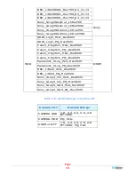
Page 17: ...turn it on again 7 In this menu set Camera LUT Type to USER 8 Set USER to the storage location you chose in step 4 Table 2 7 Supported Camera LUTs Camera LUT Look Up Table LUT Name Company ARRI_LogC_...

Page 18: ..._HLG_Rec2020 Canon_Clog2Cin_PQ_Rec2020 Canon_Clog3Cin_HLG_Rec2020 Canon_Clog3Cin_PQ_Rec2020 Panasonic_VLog_HLD_Rec2020 Panasonic_VLog_PQ_Rec2020 RED_L3G10_HLG_Rec2020 RED_L3G10_PQ_Rec2020 Sony_SLog3_C...

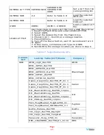
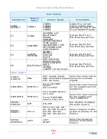
Page 19: ...ASSIST PEAK ZEBRA UNDEF no function Set up the F4 U4 Function key action Menu Page 2 AUDIO SOURCE EBD EXT Analog Inputs EBD Embedded Signal OFF No audio Select the audio source among the available si...

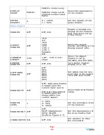
Page 20: ...00 in 0 01 steps When the Aspect Marker is set to Variable use this ratio CENTER MARKER OFF OFF ON Turn center marker display on or off SAFE AREA MARKER OFF OFF 80 85 88 90 93 95 Set safety marker si...

Page 21: ...position for the waveform display according to Waveform Size VECTOR SCOPE OFF OFF ON Enable or disable vectorscope display VECTOR SCOPE LOCATION TOP RIGHT LEFT UP CENTER UP RIGHT UP RIGHT CENTER RIGHT...

Page 22: ...lue in image Larger value means more detail detection PEAK OFF OFF ON Enable or Disable Peak function Over sharpen the image PEAK LEVEL 1 1 8 Set the sharpness level Higher value gives a sharper image...

Page 23: ...ATUS DISPLAY OFF OFF ON AUTO Set the timeout of the Status Information display LANGUAGE ENGLISH ENGLISH CHINESE Set product language MONITOR RESET Use this selection with caution to reset the product...

Page 24: ...5200 2400 4800 9600 19200 38400 57600 115200 Set the BAUD rate for RS 485 communication To enter the characters for the IMD CHARACTER setting navigate to the setting and press Next Press Up or Down re...

Page 25: ...nal per screen Screen Resolution 1920 H x 1080 V Aspect ratio 16 9 4 3 Display Area mm 382 H x 215 V Viewing Angle 178 H x 178 V Color Depth 262K colors Contrast Ratio 800 1 Brightness 300 cd m2 typic...

Page 26: ...dio In L R Audio Select Video Decoding Input Select Re Gen 3G HD SD SDI 1 Out 3G HD SD SDI 2 In CVBS Video In SDI De Embed LCD 17 16 9 With 16 Channel Audio Meters System Control Audio Level Metering...

Page 27: ...X 1080i50 X 1080i60 59 94 X 1080p24 23 98 X 1080p25 X 1080p30 29 97 4 2 2 YCbCr 12 bit 4 4 4 YCbCr 10 bit 4 4 4 YCbCr 12 bit 4 4 4 RGB 10 bit 4 4 4 RGB 12 bit 4 4 4_XYZ_10 bit 4 4 4_XYZ_12 bit X 1080p...

Reviews: