Page 8
CHAPTER 2: Local Operation
The RMTF-170-3G front and rear panels are described in this chapter.
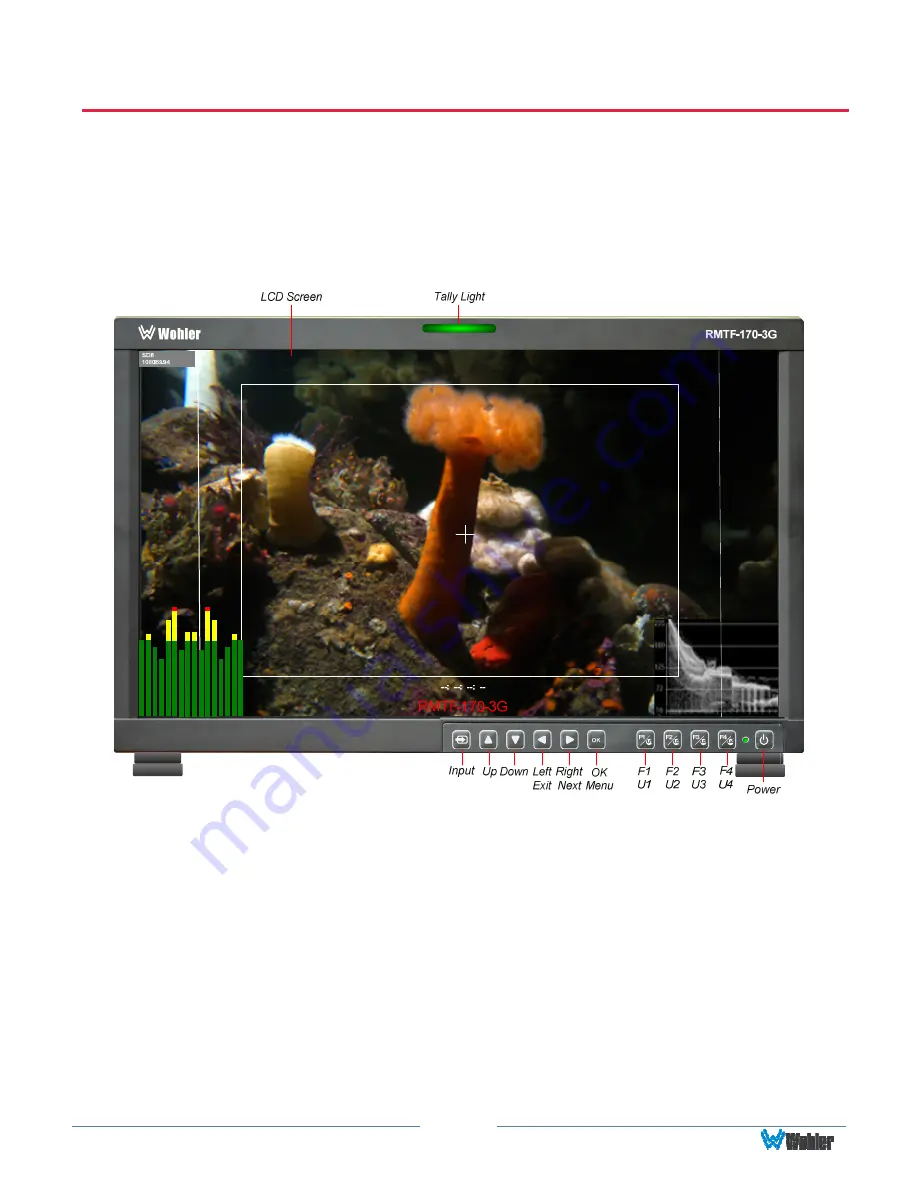
Front Panel
Figure 2–1: Front Panel Layout
1.
Tally Lights
:
This tri-color (red/green/amber) light is controlled through a RJ45
connector on the rear panel. For more information about the RJ45 connector,
refer to the Rear Panel section of this chapter. When first connected to power,
the Tally Light glows amber until the unit is ready for operation.
2.
LCD Screen
: The LCD screen displays the audio meters, waveform, vector, or
histogram displays, menus, and OSD features superimposed over the video.
3.
Power
:
The
Power
button turns the LCD screen to On or Standby mode. The
adjacent
Power Indicator
glows green to indicate On and red to indicate
Standby. To prevent the operator from accidentally switching the monitor to
Standby mode, the
Power
button must be held for 2 seconds.
4.
Input
:
The
Input
button selects the video/audio input to be monitored from the


