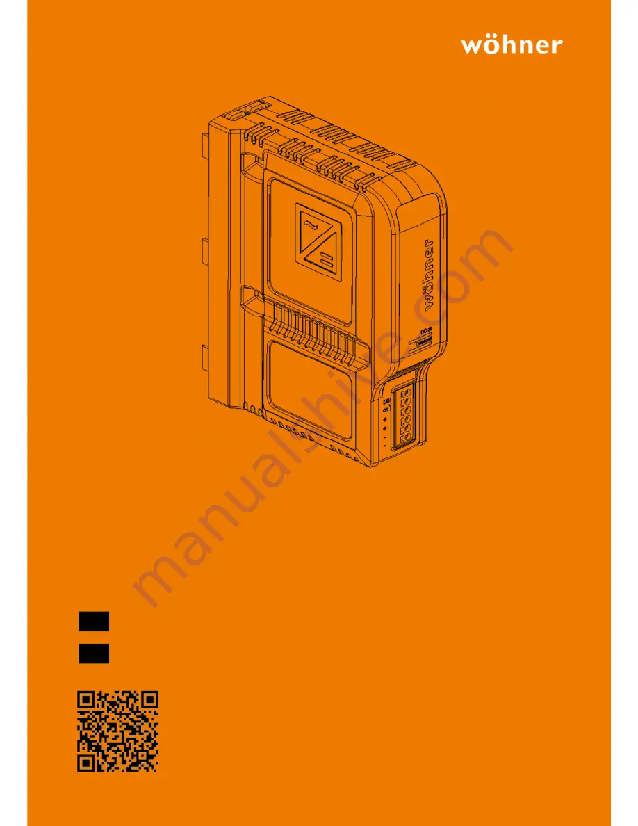
background image


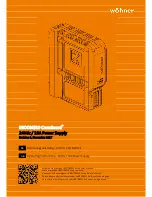
BROOME10 


BROOME10 CrossBoard

®


24Vdc / 10A Power Supply 

Revision 1, November 2017 


Bedienungsanleitung – 24Vdc / 10A Netzteil 


Operating Instructions – 24Vdc / 10A Power Supply  


Erfahren Sie mehr über BROOME10 auf unserer Website. 


Learn more about BROOME10 at our website. 


Apprenez-en davantage sur le BROOME10 sur notre site Internet. 


Potete trovare ulteriori informazioni su BROOME10 alla nostra homepage. 


Encontrará más información sobre BROOME10 en nuestra página web.


DE 

GB 

Summary of Contents for BROOME10

Page 1: ...structions 24Vdc 10A Power Supply Erfahren Sie mehr über BROOME10 auf unserer Website Learn more about BROOME10 at our website Apprenez en davantage sur le BROOME10 sur notre site Internet Potete trovare ulteriori informazioni su BROOME10 alla nostra homepage Encontrará más información sobre BROOME10 en nuestra página web DE GB ...

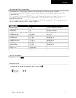
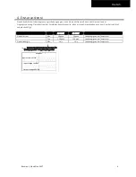
Page 2: ...t und 25 C Umgebungstemperatur und nach 5 Minuten Einlaufzeit sofern nicht anders angegeben Technische Daten Ausgangsspannung DC 24V 0 6 über den gesamten Lastbereich Spannungsregelung Ausgangsstrom 10A Unter 50 C Umgebung 5A Bei 70 C Umgebung Derating linear zwischen 50 C und 70 C Eingangsspannung AC AC 380 480V 10 15 Netzfrequenz 50 60Hz 6 Eingangsstrom AC 0 77 0 62A Bei 400 480Vac Leistungsfakt...

Page 3: ...fahrung zusammengetragen Sofern nicht ausdrücklich etwas anderes vereinbart wurde stellen diese Informationen keine Garantie im rechtlichen Sinn des Wortes dar Da sich der Stand unserer Kenntnisse und Erfahrungen ständig ändert unterliegen die Angaben in diesem Datenblatt einer Überarbeitung Wir bitten Sie daher immer die neueste Ausgabe dieses Dokuments zu verwenden konsultieren Sie Wöhner Kein T...

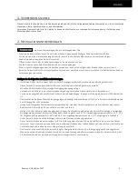
Page 4: ...pannung anliegt Verwenden Sie das Gerät in einer kontrollierten Umgebung Verwenden Sie das Gerät nicht in Bereichen mit Verschmutzungsgrad 3 ohne zusätzlichen Schutz oder in Anwendungen in denen ein Schutzgrad besser als IP30 erforderlich ist Das Gerät ist für die Konvektionskühlung ausgelegt und benötigt keinen externen Lüfter Den Luftstrom nicht behindern und das Lüftungsgitter nicht verdecken H...

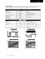
Page 5: ...ngangsstrom Typ 0 77A 0 62A Bei 24V 10A siehe Fig 3 3 Leistungsfaktor Typ 0 70 0 73 Bei 24V 10A siehe Fig 3 4 Nach DIN 40110 2 für 3 phasige Systeme Einschaltverzögerung Typ 200ms 200ms Siehe Fig 3 2 Anstiegszeit Typ 55ms 55ms Bei 24V 10A ohmsche Last 0mF Lastkapazität siehe Fig 3 2 Typ 90ms 90ms Bei 24V 10A ohmsche Last 10mF Lastkapazität siehe Fig 3 2 Überschwingen beim Einschalten Max 200mV 200...

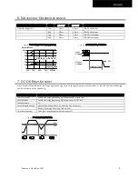
Page 6: ... ersten Mikrosekunden nach dem Einschalten bleibt unberücksichtigt AC 400V AC 480V Einschaltstrom Max 2Apeak 2Apeak Unabhängig von der Temperatur Typ 1 5Apeak 1 5Apeak Unabhängig von der Temperatur Einschaltenergie Max 1A s 1A s Unabhängig von der Temperatur Fig 4 1 Typisches Einschaltverhalten bei Nennlast 400 Vac Eingang und 25 C Umgebungstemperatur Input voltage1kV DIV Output voltage20V DIV Inp...

Page 7: ...uerstrom Ausgangsspannung über 13Vdc siehe Fig 5 1 HiccupPLUS Modus Ausgangsspannung unter 13Vdc siehe Fig 5 1 und Fig 5 2 Das Netzteil liefert einen kontinuierlichen Ausgangsstrom für 2 8s Danach wird der Ausgang für 7s ausgeschaltet bevor automatisch ein neuer Startversuch über 1 2s durchgeführt wird Dieser Zyklus wird wiederholt solange die Überlastung vorhanden ist Wenn die Überlast behoben wu...

Page 8: ...abhängig von der rückgespeisten Spannung Kontakt schließt Sobald die Ausgangsspannung typischerweise 20V erreicht hat Kontakt öffnet Sobald die Ausgangsspannung typischerweise unter 19V fällt Schalthysterese 1V Kontaktbelastbarkeiten Maximal 60Vdc 0 3A 30Vdc 1A 30Vac 0 5A ohmsche Last Minimale zulässige Belastung 1mA bei 5Vdc Isolationsspannung Siehe Spannungsfestigkeitstabelle in Kapitel 17 Fig 7...

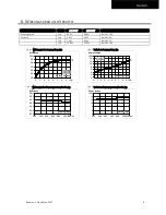
Page 9: ...ngsstrom typ Fig 8 3 Wirkungsgrad zu Eingansgspannung bei 10A typ Fig 8 4 Verluste zu Eingangsspannung bei 10A typ E fficiency 2 92 94 95 90 96 10A 4 7 8 6 Output C urrent 9 5 3 93 91 a a 400Vac b 480Vac b P ower L os ses 0 2 4 8 9 10A 0 2 6 8 12 14 16W 4 6 10 7 5 3 1 Output C urrent a b a 400Vac b 480Vac E fficiency 320 360 400 440 480 96 93 5 94 5 95 5 95 0 94 0 93 0 520 560Vac Input Voltage P o...

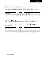
Page 10: ...ischen Gerätefehlern berechnet wird und die Zuverlässigkeit eines Geräts angibt Es ist die statistische Darstellung der Wahrscheinlichkeit dass eine Einheit ausfällt und repräsentiert nicht notwendigerweise die Lebensdauer eines Produkts Die MTBF Zahl ist eine statistische Darstellung der Wahrscheinlichkeit dass ein Gerät ausfällt Eine MTBF Zahl von z B 1 000 000h bedeutet dass statistisch gesehen...

Page 11: ...e 2 3mm Abisolierlänge 10mm 0 4Zoll Schraubendreher 3 0mm Schlitzschraubendreher um die Feder zu öffnen Anweisungen für die Verdrahtung a Verwenden Sie geeignete Kupferkabel die für minimale Betriebstemperaturen ausgelegt sind von 60 C für Umgebungstemperatur bis 45 C und 75 C für Umgebungstemperatur bis 60 C und 90 C für Umgebungstemperaturen bis 70 C b Beachten Sie die nationalen Installationsvo...

Page 12: ...as Gerät aufgrund von Übertemperatur ausgeschaltet wurde Die Eingangsspannung muss dafür anliegen C Output Terminals Push in Klemmen Zwei identische Pole und zwei identische Pole Positiver Ausgang Negativer Ausgang D DC OK Relay Kontakt Push in Klemmen Überwacht die Ausgangsspannung siehe Kapitel 7 für Details Output Over Voltage P rotection P F C C onverter P ower C onverter Output F ilter Output...

Page 13: ...um B Starke Transienten VDE 0160 Über den gesamten Lastbereich 1584V 1 3ms Kriterium A Kriterien A Die Stromversorgung weist ein normales Betriebsverhalten innerhalb der definierten Grenzen auf B Vorübergehender Funktions oder Leistungsverlust während der Tests schaltet sich gegebenenfalls ab und eigenständig wieder ein EMV Störaussendung Fachgrundnorm EN 61204 3 Conducted emission input lines EN ...

Page 14: ...ungskategorie T b d IEC 62477 1 Aufstellhöhen bis 2000m T b d IEC 60950 1 Aufstellhöhen von 2000m bis 4000m T b d IEC 62477 1 Aufstellhöhen von 2000m bis 4000m Verschmutzungsgrad 2 IEC 62477 1 nicht leitend LABS Kompatibilität Das Gerät setzt kein Silikon oder andere LABS kritische Substanzen frei und ist für den Einsatz in Lackierereien geeignet Hörbare Geräusche Während des Leerlaufs der Überlas...

Page 15: ...h Schutzart IP 30 EN IEC 60529 Übertemperaturschutz ja Ausgangsabschaltung mit automatischem Neustart Der Temperatursensor ist an kritischen Komponenten in der Einheit installiert und schaltet das Gerät in sicherheitskritischen Situationen aus was beispielsweise passieren kann wenn die Anforderungen für die Leistungsreduzierung nicht eingehalten werden die Umgebungstemperatur zu hoch ist die Belüf...

Page 16: ... die maximale Spannung zwischen DC OK und dem Ausgang nicht überschritten wird Spalte D Wir empfehlen die DC OK Pins und die Ausgangspins bei der Durchführung des Tests miteinander zu verbinden 18 ZULASSUNGEN EG Konformitätserklärung Das CE Zeichen zeigt die Übereinstimmung mit der EMV Richtlinie und der Niederspannungsrichtlinie UL 61010 2 201 geplant Sicherheitsanforderungen für elektrische Gerä...

Page 17: ...17 Deutsch 19 ABMESSUNGEN UND GEWICHT Breite 45mm 1 77 Höhe 160mm 6 3 Tiefe 130mm 5 12 Gewicht 550g 1 21lb Gehäusematerial T b d Einbauabstände Siehe Kapitel 2 Fig 19 1 Frontansicht Fig 19 2 Seitenansicht Alle Abmessungen in mm ...

Page 18: ...egt wird Achten Sie darauf dass Ableitstrom EMB Einschaltstrom und Oberschwingungen bei Verwendung mehrerer Netzteile zunehmen 20 3 PARALLELBETRIEB ZUR LEISTUNGSERHÖHUNG Eine Parallelschaltung von Stromversorgungen für höhere Ausgangsleistung ist für Umgebungstemperaturen bis 45 C zulässig Das Gerät verfügt über eine Soft Output Regelcharakteristik Parallel Use Mode um eine Stromaufteilung zwische...

Page 19: ...erature range Technical Data Output voltage DC 24V 0 6 over entire load range Adjustment range Output current 10A Below 50 C ambient 5A At 70 C ambient Derate linearely between 50 C and 70 C Input voltage AC AC 380 480V 10 15 Mains frequency 50 60Hz 6 Input current AC 0 77 0 62A At 400 480Vac Power factor 0 70 0 73 At 400 480Vac Input inrush current 1 5 1 5Apk At 400 480Vac Efficiency 94 9 94 8 At...

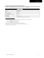
Page 20: ...and has the same meaning as the symbol Earth Ground This document uses the term earth which is the same as the U S term ground T b d To be defined value or description will follow later AC 400V A figure displayed with the AC or DC before the value represents a nominal voltage with standard tolerances usually 15 included E g DC 12V describes a 12V battery disregarding whether it is full 13 7V or fl...

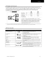
Page 21: ...evice in a controlled environment Do not use the device in pollution degree 3 areas without additional protection or in applications where a degree of protection better than IP30 is required The device is designed for convection cooling and does not require an external fan Do not obstruct airflow and do not cover ventilation grid Keep the following minimum installation clearances when the device i...

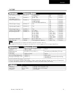
Page 22: ...r 2 AC 400V AC 480V Input current Typ 0 77A 0 62A At 24V 10A see Fig 3 3 Power factor Typ 0 70 0 73 At 24V 10A see Fig 3 4 According to DIN 40110 2 for 3 phase systems Start up delay Typ 200ms 200ms See Fig 3 2 Rise time Typ 55ms 55ms At 24V 10A resistive load 0mF load capacitance see Fig 3 2 Typ 90ms 90ms at 24V 10A resistive load 10mF load capacitance see Fig 3 2 Turn on overshoot Max 200mV 200m...

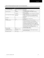
Page 23: ...ression capacitors is disregarded in the first microseconds after switch on AC 400V AC 480V Inrush current Max 2Apeak 2Apeak Temperature independent Typ 1 5Apeak 1 5Apeak Temperature independent Inrush energy Max 1A s 1A s Temperature independent Fig 4 1 Typical turn on behaviour at nominal load 400Vac input and 25 C ambient Input voltage1kV DIV Output voltage20V DIV Input current 1A DIV 40ms DIV ...

Page 24: ...eeded Overload behaviour Continuous current Output voltage above 13Vdc see Fig 5 1 HiccupPLUS mode Output voltage below 13Vdc see Fig 5 1 and Fig 5 2 The power supply delivers continuous output current for 2 8s After this the output is switched off for 7s before a new start attempt with 1 2s is automatically performed This cycle is repeated as long as the overload exists If the overload has been c...

Page 25: ...independent of back fed voltage Contact closes As soon as the output voltage reaches typically 20V Contact opens As soon as the output voltage falls below typically 19V Switching hysteresis 1V Contact ratings Maximal 60Vdc 0 3A 30Vdc 1A 30Vac 0 5A resistive load Minimal permissible load 1mA at 5Vdc Isolation voltage See dielectric strength table in chapter 17 Fig 7 1 DC ok relay contact behavior 0...

Page 26: ...output current typ Fig 8 3 Efficiency vs input voltage at 10A typ Fig 8 4 Losses vs input voltage at 10A typ E fficienc y 2 92 94 95 90 96 10A 4 7 8 6 Output C urrent 9 5 3 93 91 a a 400Vac b 480Vac b P ower Los ses 0 2 4 8 9 10A 0 2 6 8 12 14 16W 4 6 10 7 5 3 1 Output C urrent a b a 400Vac b 480Vac E fficiency 320 360 400 440 480 96 93 5 94 5 95 5 95 0 94 0 93 0 520 560Vac Input Voltage P ower L ...

Page 27: ... Between Failure which is calculated according to statistical device failures and indicates reliability of a device It is the statistical representation of the likelihood of a unit to fail and does not necessarily represent the life of a product The MTBF figure is a statistical representation of the likelihood of a device to fail A MTBF figure of e g 1 000 000h means that statistically one unit wi...

Page 28: ...24 12 Max wire diameter including ferrules 2 3mm Wire stripping length 10mm 0 4inch Screwdriver 3 0mm slotted to open the spring Instructions for wiring a Use appropriate copper cables that are designed for minimum operating temperatures of 60 C for ambient up to 45 C and 75 C for ambient up to 60 C and 90 C for ambient up to 70 C minimum b Follow national installation codes and installation regul...

Page 29: ...ng when the device has switched off due to over temperature Input voltage is required C Output Terminals push in terminals two identical poles and two identical poles Positive output Negative return output D DC OK Relay Contact push in terminals Monitors the output voltage see chapter 7 for details Output Over Voltage P rotection P F C C onverter P ower C onverter Output F ilter Output P ower Mana...

Page 30: ...0 4 11 0 of 380Vac 0V 5000ms Criterion B Powerful transients VDE 0160 Over entire load range 1584V 1 3ms Criterion A Criterions A Power supply shows normal operation behavior within the defined limits B Temporary loss of function or performance during the tests self recoverable EMC Emission According to EN 61204 3 Conducted emission input lines EN 55011 EN 55015 EN 55022 FCC Part 15 CISPR 11 CISPR...

Page 31: ...ng to IEC 62477 1 for altitudes up to 2000m T b d According to IEC 60950 1 for altitudes from 2000m to 4000m T b d According to IEC 62477 1 for altitudes from 2000m to 4000m Degree of pollution 2 According to IEC 62477 1 not conductive LABS compatibility The unit does not release any silicone or other LABS critical substances and is suitable for use in paint shops Audible noise Some audible noise ...

Page 32: ... A PE Protective Earth connection is not required Degree of protection IP 30 EN IEC 60529 Over temperature protection Yes Output shut down with automatic restart The temperature sensor is installed on critical components inside the unit and turns the unit off in safety critical situations which can happen e g when de rating requirements are not observed ambient temperature is too high ventilation ...

Page 33: ...is not exceeded column D We recommend connecting DC OK pins and the output pins together when performing the test 18 NORMS AND APPROVALS EC Declaration of Conformity The CE mark indicates conformance with the EMC directive and the Low voltage directive LVD UL 61010 2 201 planned Safety Requirements for Electrical Equipment for Measurement Control and Laboratory Use Part 2 201 Particular Requiremen...

Page 34: ...English 19 PHYSICAL DIMENSIONS AND WEIGHT Width 45mm 1 77 Height 160mm 6 3 Depth 130mm 5 12 Weight 550g 1 21lb Housing material T b d Installation clearances See chapter 2 Fig 19 1 Front view Fig 19 2 Side view All dimensions in mm ...

Page 35: ...t leakage current EMI inrush current harmonics will increase when using multiple power supplies 20 3 PARALLEL USE TO INCREASE OUTPUT POWER A parallel connection of power supplies for higher output power is allowed for ambient temperatures up to 45 C The device is featured with a soft output regulation characteristic Parallel Use Mode in order to achieve current share between multiple devices when ...

Reviews: