English
Broome 10 Installation Manual
6
3. UL notes
WARNING: Risk of electrical shock and fire
The opening of the branch-circuit protective device may be an
indication that a fault current has been interrupted.
To reduce the risk of fire or electric shock, current-carrying parts
and the other components of the controller should be examined
and replaced if damaged.
Failure to follow instructions can result in death, serious injury, or
equipment damage.
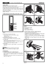
4. Operating and indicating elements
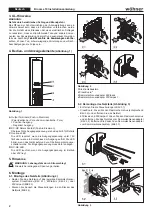
(Figure 1)
Figure 1
A
Output Terminals (push-in terminals)
(Two ide poles and two identical - poles)
+ Positive output
– Negative (return) output
B
DC-OK Relaiy Contact (push-in terminals)
Monitors the output voltage, see chapter 8 for details.
C
Overload LED
The LED is on when the output voltage falls below 19 V or in
case of a short circuit in the output.
The LED is flashing when the device has switched off due to
over- temperature. Input voltage is required.
D
DC-OK LED
The LED is on when the output voltage of a running device is
above 20 V.
5. Notes
WARNING: Danger to life by electric shock
Never carry out work when voltage is present.
6. Mounting
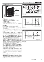
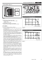
6.1. Mounting the power supply (Figure 2)
• Snap the power supply unit onto the respective system Cross
-
Board
®
(Subfig. 2.1), 60Classic (Subfig. 2.2) or 30Compact
(Subfig. 2.3).
• Then insert the control wires into the control plug of the power
supply unit (Subfig. 2.4).
Figure 2
1
Electronic power supply
2
CrossBoard
®
3
bubar adapter 60Classic
4
busbar adapter 30Compact
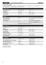
6.2. Dismounting the power supply (Figure 3)
• Remove the control wires (Subfig. 3.1.).
• CrossBoard
®
: Loosen the latching mechanism (corresponding
Subfig. 3.2) and remove the power supply unit.
• 60Classic and 30Compact: Loosen the latching mechanism
and remove the power supply unit from the busbar adapter
(Subfig. 3.2).
• Then remove the busbar adapter from the busbar system
(Subfig. 3.3).
Figure 3


