background image

A

D

E

f

D

49

W415-1600 / 06.01.16

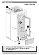
The images are for illustration purposes

A

Exhaust motor (disassembly and cleaning and exhaust pipe), new silicone (Red RTV) in required points

B

Inspection of gaskets, ash drawer and burn pot door (replace them and apply silicone (Red RTV) where required)

C

Combustion chamber (total cleaning of the entire chamber) and ignition plug pipe cleaning

D

Hopper (complete emptying and clean)

E

Room air fan disassembly and removal of dust and any pellet debris

f

Air intake pipe inspection and any flow sensor cleaning

Summary of Contents for Vicenza V5.2

Page 1: ...not start a fire with chemicals or fluids such as gasoline engine oil etc Do not burn trash or garbage lawn clippings waste rubber waste petroleum products paints or paint thinners solvents plastic ma...

Page 2: ...2 installing the pellet vent 16 5 3 VENTING THE PELLET APPLIANCE 16 5 4 PELLET VENT TERMINATION 16 5 5 VENT TERMINAL CLEARANCES 17 6 0 Ducting installation 20 7 0 WIRING DIAGRAM 21 8 0 Ceramic INSTALL...

Page 3: ...2 19 3 SOOT AND FLY ASH FORMATION 42 19 4 DAILY 43 19 5 WEEKLY 45 19 6 MONTHLY 46 19 7 ROUTINE MAINTENANCE CARRIED OUT BY AUTHORIZED TECHNICIANS 47 19 8 PUTTING THE EQUIPMENT OUT OF SERVICE END OF THE...

Page 4: ...1600 06 01 16 1 0 INSTALLATION OVERVIEW Rating Plate see RATING PLATE INFORMATION SECTION CONTROL PANEL See CERAMIC INSTALLATION SECTION Floor see INSTALLATION PLANNING FLOOR PROTECTION REQUIREMENTS S...

Page 5: ...ken Replacement of the glass should be done by a licensed or qualified service person The viewing door and ash pan must be closed and latched during operation Do not strike or slam shut the appliance...

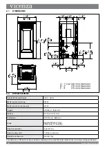
Page 6: ...6 W415 1600 06 01 16 2 2 SPECIFICATIONS Electrical Rating 120V 60Hz Watts During Start Up Sequence 397 W Watts During Operation 213 W Width 22 3 64 560 mm Height 44 1 8 1121 mm Depth 22 51 64 580 mm W...

Page 7: ...before installation and use of this pellet fuel burning room appliance Failure to follow these instructions could result in property damage bodily injury or even death Keep this manual handy for futu...

Page 8: ...THE USE OF PELLETS THAT MEET OR EXCEED THESE STANDARDS ASK YOUR DEALER FOR A RECOMMENDED PELLET TYPE The pellet HOPPER lid must always be closed during appliance operation Pellet quality is important...

Page 9: ...appliance will automatically switch off and will show the alarm PELLET HOPPER OPEN In order to restart the appliance and then reach START UP phase the conditions must be corrected and reset close pell...

Page 10: ...CLEAN 3 1 Fire poker This appliance is equipped with a fire poker figure 1 which facilitates operations like opening closing door and cleanings see CLEANING AND MAINTENANCE section On the back side o...

Page 11: ...for any permits required for installation of this pellet appliance and notify your insurance company before proceeding with installation Be mindful of wind conditions when locating the appliance to m...

Page 12: ...A HAVING LESS THAN 20 508mm CLEARANCE FROM CEILING TO APPLIANCE TOP 4 2 1 CORNER INSTALLATION Through the wall installations Interior Vertical Vents Through the wall installation Interior Vertical Ven...

Page 13: ...manner inconsistent with the operating instructions in this manual can increase the smoke and the carbon monoxide CO emissions considerably We recommend having monitors for areas that are expected to...

Page 14: ...me should be installed in accordance with the current Manufactured Home Construction and Safety Standard Title 24 CFR Part 3280 in the United States or the Mobile Home Standard CAN CSA Z240 MH Series...

Page 15: ...SECURING kit FIGURE 2 15 W415 1600 06 01 16...

Page 16: ...arallel or above the exhaust output of the pellet appliance It is recommended that at least 3 0 9m of vertical pipe be installed to create some natural draft This is to help prevent the possibility of...

Page 17: ...tible corner wall or protruding combustible obstructions vent chase etc F 9 0 23 Clearance to a non mechanical air supply inlet to the building or a combustion air inlet to any other appliance G 3 0 9...

Page 18: ...llation showing inlet of outside air in ventilated crawl space SEE VENT MANUFACTURER S INSTRUCTIONS SEE VENT MANUFACTURER S INSTRUCTIONS NOTE FOLLOW VENT MANUFACTURER S SPECIFICATIONS INSTALLATION TYP...

Page 19: ...NT MANUFACTURER S INSTRUCTIONS 6 152 mm Outside Air Recommended Wall Thimble Wall Thimble Outside Air Recommended NOTE FOLLOW VENT MANUFACTURER S SPECIFICATIONS INSTALLATION TYPE 2 Set the appliance a...

Page 20: ...the intent is to simply discharge hot air straight out the back of the appliance a 36 clearance to combustibles must be maintained from the rear of the appliance WITH DUCTING INSTALLED 3 aluminum rigi...

Page 21: ...ANCE INSPECTED FOR DAMAGE TO THE ELECTRICAL CIRCUIT RISK OF ELECTRICAL SHOCK OR EXPLOSION DO NOT WIRE 120V TO THE VALVE OR TO THE APPLIANCE WALL SWITCH INCORRECT WIRING WILL DAMAGE CONTROLS ALL WIRING...

Page 22: ...1 x 4 x package 8 0 Ceramic INSTALLATION 1 x 2 x CAUTION CERAMIC PARTS ARE EXTREMELY FRAGILE HANDLE WITH CARE 22 W415 1600 06 01 16...

Page 23: ...REMOVE TRIVET TRIVET OUTER TOP OPEN HOPPER DOOR REMOVE SCREWS 4 SECURING OUTER TOP AND SET ASIDE 1 2 23 W415 1600 06 01 16...

Page 24: ...ND INSTALL LOWER PANEL BY ENGAGING TABS INTO SLOTS AND SECURING 2 SCREWS PROVIDED INTO THE TOP PLACE CERAMIC SIDE PANEL FLUSH AGAINST APPLIANCE AND SLIDE DOWN ONTO 4 SECURING BRACKETS ALL 4 SIDES ARE...

Page 25: ...ERAMIC TOP PLACE CERAMIC TOP NOTE WHEN CENTERING ENSURE DIMPLES ON THE UNDERSIDE ENGAGE HOLES ON THE APPLIANCE 6 OUTER TOP replace OUTER TOP AND SECURE WITH screws REMOVED IN STEP 2 25 W415 1600 06 01...

Page 26: ...TRIVET 7 REPLACE TRIVET 26 W415 1600 06 01 16...

Page 27: ...9 0 FLAME GUARD INSTALLATION INSTALL THE FLAME GUARD ON THE BURN POT FLAME GUARD BURN POT 27 W415 1600 06 01 16...

Page 28: ...aged or malfunctions The functions that can be managed from the manual control are L1 Yellow LED LED off radio communication not available LED on radio communication available L2 Red LED LED off norma...

Page 29: ...mostat is reached open contact the ducting motor will switch to the 1st speed Z1 MODE set to eco Set the set zone Z1 to OFF Until the desired temperature is reached closed contact the ducting motor wi...

Page 30: ...ion must be performed by AN AUTHORIZED TECHNICIAN To install and activate A mechanical or digital thermostat is required Disconnect power supply Using the figure to the side as a reference connect the...

Page 31: ...GURED with unit 0 in the event there is another APPLIANCE To avoid interferences A NEW CONFIGURATION MUST BE PERFORMED modifying one of the two APPLIANCES Some radio frequency devices e g mobilE phone...

Page 32: ...m SLEEP mode 7 Serial cable input 8 Battery compartment The handheld is fitted with an LCD backlit display The display remains lit for 5 seconds After a certain period of time in order to minimize bat...

Page 33: ...DISPLAY time TEMPERATURE DETECTED IN ROOM Chrono Standby active Z1 Z2 active ROOM TEMPERATURE IN REQUEST Alarm error present NO IGNITION identification of alarm error Indicates contact of external su...

Page 34: ...delta t installation type appliance status TECHNICAL MENU TECHNICIANS ONLY Basic instructions The following recommendations must be followed the first time the appliance is ignited It is possible tha...

Page 35: ...ime to be set settings set clock xx xx dd mm yy Date and time setting language ita eng fr Language setting 14 2 language setting This menu allows the preferred language to be selected J clean check up...

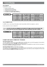
Page 36: ...ed it will automatically switch to the minimum power level or turn off activating the Standby function reducing pellet consumption to a minimum By factory default the STBY function is always set to OF...

Page 37: ...XCESS FUEL the appliance develops a very high flame even at LOW TA power levels the viewing glass becomes very dirty almost completely obscured the burn pot tends to become encrusted blocking the air...

Page 38: ...rent appliance time slots to be enabled disabled Set temperature Enabled days Disabled days 1 Monday 7 Sunday Programming 1 Ignition time Switch off time Activated Not activated Programming 3 Programm...

Page 39: ...the ducting motor will turn off set zone Z1 This setting allows configuration for the use of a room thermostat or room probe model NTC 10K to control the temperature of room Z1 off configured for use...

Page 40: ...f the room temperature exceeds the set value plus DELTAT OFF and the Stby function is active ON the appliance will switch off after a pre set default delay period and standby will be displayed on the...

Page 41: ...rature DELTA T ON hysteresis if it is not managed by an external thermostat The DELTA T ON OFF range is OFF C 33 42 F 0 5 5 5 C Z1 MODE set to ON Set the desired temperature on the set zone Z1 from 44...

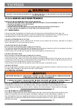
Page 42: ...eramic glass is allowed only when the glass is completely cold To clean the ceramic glass simply use a dry brush and some damp newspaper dabbed in the ash If the glazing is very dirty only use a speci...

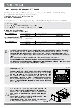
Page 43: ...SCRAPER RODS BECOME VERY HOT DURING OPERATION WAIT UNTIL Appliance HAS COOLED COMPLETELY OR WEAR HEAT RESISTANT GLOVES WHEN CLEANING OR HANDLING THIS APPLIANCE Cleaning THE HEAT EXCHANGER TUBES Use th...

Page 44: ...sh it towards the hearth wall 6 If there is an ash collector tray vacuum the ash deposits PLEASE NOTE Use a suitable vacuum cleaner with a special container to separate the collected ash WARNING THE F...

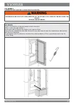
Page 45: ...If there is a lower door open remove it Take the removable ash drawer out and empty it into a special container Vacuum the area underneath the removable ash drawer Once you have cleaned it place the r...

Page 46: ...nd top walls and take the hearth wall out B and clean with the poker C and a suitable vacuum cleaner D When cleaning has been completed reposition the removable hearth wall B and secure it again with...

Page 47: ...rrect combustion in the appliance over time thereby preventing any anomalies and or malfunctions that may require more work to be performed by the technician Requests for routine maintenance are not c...

Page 48: ...n required points B Inspection of gaskets ash drawer and burn pot door replace them and apply silicone Red RTV where required C Combustion chamber total cleaning of the entire chamber and ignition plu...

Page 49: ...ints B Inspection of gaskets ash drawer and burn pot door replace them and apply silicone Red RTV where required C Combustion chamber total cleaning of the entire chamber and ignition plug pipe cleani...

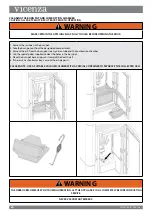
Page 50: ...ce switches off it is necessary to wait for the complete shutdown of the exhaust motor before cleaning the burn pot The appliance can only be reignited when these operations have been performed Cool S...

Page 51: ...pellet flow see PELLET FEED ADJUSTMENT section Ensure all cleaning and maintenance has been carried out see CLEANING AND MAINTENANCE section Place the burnpot so that the locating notch engages with t...

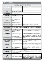
Page 52: ...rly Refer to the VENTING section in the manual to determine where the venting system is installed incorrectly Burnpot holes are blocked Remove the burnpot and thoroughly clean it Blockage in air intak...

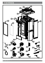
Page 53: ...ER COMBUSTION V5 2 002271075 SER YES 8 BLOWER CONVECTION ZONE 1 V5 2 002271076 SER YES 9 BLOWER CONVECTION ZONE 2 V5 2 002271077 SER YES 10 BLOWER CONVECTION ROOM V5 2 002271078 SER YES 11 CONTROL BAC...

Page 54: ...55 W415 1600 06 01 16 15 21 17 16 20 18 19 16 6 7 10 8 9 13 11 14 3 4 12 1 5 2 24 23 22 26 28 27 25 30 29...

Page 55: ...er damage long periods of dampness condensation damaging chemicals or cleaners will not be the responsibility of VICENZA Regular cleaning of the ne ash generated during the operation of this appliance...

Page 56: ...57 W415 1600 06 01 16 24 0 NOTES 44 1...

Page 57: ...58 W415 1600 06 01 16 44 1...

Page 58: ...flame distributed by Wolf Steel Ltd The Manufacturer reserves the right to vary the features and data shown in this booklet at any time and without prior notice in order to improve its products This m...

Page 59: ...ermis d installation Reinseignez vous aupr s des autorit s locales du b timent ou du service des incendies au sujet des restrictions et des exigences d inspections des l installation Cet appareil est...

Page 60: ...TERMINAISON HORIZONTAL 18 6 0 INSTALLATION DES CONDUITS 19 7 0 SCH MA DE C BLAGE 20 8 0 INSTALLATION DE LA C RAMIQUE 21 9 0 iNSTALLATION DE GARDE FLAMME 26 10 0 D TAILS DU V5 2 27 10 1 PANNEAU DE CON...

Page 61: ...gation voir la section information sur la plaque d homologation PANNEAU DE COMMANDE Voir la section PRISE D AIR EXT RIEUR Plancher voir la section PLANIFICATION DE L INSTALLATION PROTECTION DU PLANCHE...

Page 62: ...es doivent demeurer ferm s et verrouill s durant le fonctionnement Ne frappez pas et ne claquez pas la porte vitr e de l appareil Seules les portes fa ades certifi es pour cet appareil peuvent tre uti...

Page 63: ...air 1 57 64 po 48 mm Capacit du r servoir 59 lb 27 kg 4 3 4 14 916 9 3 32 8 5 16 4 3 4 20 25 32 3 31 32 18 5 8 4 11 32 22 3 64 560 mm 44 1 8 11201 mm 22 51 64 579 mm A 1 48 mm Diameter B 3 76 mm Diame...

Page 64: ...cet appareil d une mani re incompatible avec les instructions de ce manuel de fonctionnement L enveloppe de protection sur les parties plaqu es mieux dispara t lorsque l Assembl e est temp rature ambi...

Page 65: ...ourquoi l appareil a surchauff INTERRUPTEUR DE BASSE TEMP RATURE Cet interrupteur teindra automatiquement l appareil dans l ventualit que le feu s teigne ou que l appareil ne s allume pas en 15 minute...

Page 66: ...uement et affichera le message d alarme R SERVOIR DE COUVERCLE OUVERT Pour red marrer l appareil et lui permettre d atteindre la phase de D MARRAGE les probl mes doivent tre corrig s et le bon fonctio...

Page 67: ...est muni d un tisonnier figure 1 ce qui facilite les op rations telles que l ouverture et la fermeture de la porte ainsi que le nettoyage voir la section NETTOYAGE ET ENTRETIEN l arri re de l appareil...

Page 68: ...RATION POURRAIT CAUSER UN INCENDIE OU DES BLESSURES N UTILISEZ QUE LES ACCESSOIRES OPTIONNELS ET LES PI CES DE RECHANGE APPROUV S PAR VICENZA POUR CET APPAREIL L UTILISATION D ACCESSOIRES ET DE PI CE...

Page 69: ...ERTISSEMENT AVERTISSEMENT Installations travers le mur vents verticaux int rieurs Installation travers un mur vents verticaux int rieurs VOIR LES INSTRUCTIONS DU FABRICANT D VENT VOIR LES INSTRUCTIONS...

Page 70: ...elles en par ticulier pour les r sidences co nerg tiques et tanches L alimentation en air ext rieur ne doit pas d passer 8 pi 2 4 m de longueur Les prises d air ext rieur doivent tre compos es d un co...

Page 71: ...r de la maison mobile certains tats ne l exigent pas consultez les autorit s locales du b ti ment AVERTISSEMENT NE PAS INSTALLER DANS UNE CHAMBRE COUCHER L INT GRIT STRUCTURALE DU PLANCHER DES MURS ET...

Page 72: ...14 W415 1600 06 01 16 KIT DE FIXATION FIGURE 2...

Page 73: ...8 85 7mm Scellez chaque joint en appliquant une quantit g n reuse de silicone RTV 500 F 260 C Nous vous conseillons de sceller l ext rieur des connexions du syst me d vacuation afin de faciliter l ac...

Page 74: ...3 0 9m D gagement d une prise d air m canique H 7 2 1m D gagement au dessus d un trottoir ou d une entr e pav e situ sur une propri t publique I 12 304 8mm D gagement sous une v randa une terrasse en...

Page 75: ...pareil conform ment l installation existante Type 1 terminaison verticale type 2 terminaison horizontale Voir la section TYPE D INSTALLATION NOTE RESPECTEZ LES SP CIFICATIONS DU FABRICANT INSTALLATION...

Page 76: ...IFICATIONS DU FABRICANT INSTALLATION DE TYPE 2 Configurez l appareil conform ment l installation existante Type 1 terminaison verticale type 2 terminaison horizontale Voir la section TYPE D INSTALLATI...

Page 77: ...appareil AVEC INSTALLATION DE CONDUITS Un conduit flexible de 3 po en aluminium peut tre utilis pour connecter la sortie d air chaud un diffuseur grille condition qu il y ait un minimum de 36 po et un...

Page 78: ...GERA LES CONTR LES CET APPAREIL DOIT TRE RACCORD LECTRIQUEMENT PAR UN LECTRICIEN QUALIFI CONFORM MENT AUX CODES LOCAUX EN L ABSENCE DE CODES LOCAUX UTILISEZ LA VERSION COURANTE DU CODE CANADIEN DE L L...

Page 79: ...21 W415 1600 06 01 16 1 x 4 x PAQUET 1 x 2 x ATTENTION LES PI CES EN C RAMIQUE SONT EXTR MEMENT FRAGILES MANIPULER AVEC PR CAUTION 8 0 INSTALLATION DE LA C RAMIQUE...

Page 80: ...22 W415 1600 06 01 16 enleveZ LA GRILLE OUVREZ LA PORTE DU R SERVOIR ENLEVEZ LES VIS QUI FIXENT LE DESSUS EXT RIEUR ET METTRE DE C T GRILLE DESSUS EXT RIEUR...

Page 81: ...NEAU INF RIEUR EN ENGAGEANT LES LANGUETTES DANS LES FENTES ET EN VISSANT LES 2 VIS FOURNIES SUR LE DESSUS PLACEZ LE PANNEAU EN C RAMIQUE CONTRE L APPAREIL ET FAITES GLISSER VERS LE BAS SUR 4 SUPPORTS...

Page 82: ...N C RAMIQUE PLACER DESSUS EN C RAMIQUE REMARQUE LORSQUE LE CENTRAGE ASSURER LES FOSSETTES SUR LES DESSOUS DES TROUS S ENGAGER SUR L APPAREIL DESSUS EXT RIEUR remplacer la DESSUS EXT RIEUR ET FIXEZ AVE...

Page 83: ...25 W415 1600 06 01 16 GRILLE REMPLACER LA GRILLE...

Page 84: ...26 W415 1600 06 01 16 INSTALLEZ LE PROT G E FLAMME SUR LE BR LEUR PROT GE FLAMME BR LEUR 9 0 iNSTALLATION DE GARDE FLAMME...

Page 85: ...ntr le manuel L1 DEL jaune DEL teinte communication radio non disponible ALLUM E communication radio disponible L2 DEL rouge DEL teinte fonctionnement normal ALLUM E alarme en fonction L3 DEL verte DE...

Page 86: ...premi re vitesse MODE Z1 r gl sur CO r glez la ZONE Z1 sur ARR T Le moteur du conduit respectera les r glages de l appareil jusqu ce que la temp rature d sir e soit atteinte contact ferm Lorsque la te...

Page 87: ...IT TRE EFFECTU E PAR UN TECHNICIEN AUTORIS Un thermostat m canique ou num rique est requis D branchez l alimentation l lectrique En utilisant la figure sur le c t comme r f rence connectez les deux c...

Page 88: ...VEC L UNIT 0 DANS L VENTUALIT O IL Y AURAIT UN AUTRE APPAREIL POUR VITER LES INTERF RENCES UNE NOUVELLE CONFIGURATION DOIT TRE R ALIS E EN MODIFIANT L UN DES DEUX APPAREILS CERTAINS APPAREILS RADIOFR...

Page 89: ...reil ou retour au mode VEILLE 7 Entr e du c ble en s rie 8 Compartiment piles La t l commande poss de un cran ACL r tro clairage L cran demeure allum pendant 5 secondes Apr s un certain temps afin de...

Page 90: ...E DANS LA PI CE Chrono Veille active Z1 Z2 actiF TEMP RATURE DE LA PI CE DEMAND E ALARME ERREUR PAS D ALLUMAGE IDENTIFICATION DE L ALARME ERREUR INDIQUE LE CONTACT AVEC UN THERMOSTAT EXTERNE SUPPL MEN...

Page 91: ...t type d installation TAT DE L APPAREIL MENU TECHNIQUE TECHNICIENS SEUEMENT Instructions de base Les recommandations ci dessous doivent tre respect es lorsque l appareil est allum pour la premi re foi...

Page 92: ...ve l arri re de l appareil alimente le panneau de contr le L appareil reste teint et le panneau affiche ARR T Configurez l appareil conform ment l installation existante Type 1 sortie par le toit VERT...

Page 93: ...une sonde int gr e la t l commande Lorsque la temp rature r gl e est atteinte l appareil passe automatiquement la puissance minimale ou s teint activant ainsi la fonction VEILLE et r duisant au minimu...

Page 94: ...FAIBLE TA La vitre devient tr s sale presque compl tement obscurcie Le br leur a tendance s incruster bouchant les trous d admission d air en raison de l exc s de granules les granules ne sont br l s...

Page 95: ...de la temp rature Jours activ s Jours d sactiv s 1 Lundi 7 Dimanche Programmation 1 Heure d allumage Heure d arr t Activ Desactiv Programmation 3 Programmation 4 Programmation 1 Programmation 2 Activ...

Page 96: ...onduit s arr te R GLAGE ZONE Z1 Ce r glage permet la configuration de l utilisation d un thermostat de pi ce ou d une sonde mod le NTC 10K afin de contr ler la temp rature de la pi ce Z1 ARR T configu...

Page 97: ...LLE est active MARCHE l appareil se met hors tension apr s un d lai pr r gl par d faut VEILLE s affichera l cran FONCTION DE VEILLE R GL E SUR ARR T R GLAGE PAR D FAUT Si l appareil atteint la temp ra...

Page 98: ...ure r gl e sur zone set I1 est atteinte le moteur de conduits va passer la 1ere vitesse MODE Z1 r gl sur CO R glez la temp rature d sir e pour la ZONE Z1 de 44 104 F 7 40 C R glez la temp rature d sir...

Page 99: ...Le non respect des instructions peut endommager la surface de la vitre en c ramique et annuler la garantie NETTOYAGE DU R SERVOIR Lorsque le r servoir est compl tement vide d branchez l alimentation l...

Page 100: ...bas pour liminer les r sidus qui se trouvent dans les tubes de l changeur de chaleur REMARQUE Les grattoirs doivent tre utilis s de pr f rence lorsque l appareil est froid s ils sont utilis s lorsque...

Page 101: ...sser les r sidus qui se trouvent dans le br leur 2 Sortez le br leur de son compartiment 3 Aspirez les cendres qui se trouvent dans le logement du br leur dans le tube d allumage et dans la chambre de...

Page 102: ...amovible et fermez ou replacez la porte ext rieure Dans certains appareils le compartiment cendres se trouve dans la chambre de combustion Dans ce cas ou vrez la porte et aspirez les cendres qui se tr...

Page 103: ...ux r gulier du gaz d chappement Omettre de nettoyer l changeur de chaleur aura une incidence sur les performances et le fonctionnement r gulier de l appareil Ouvrez la porte pour acc der la chambre de...

Page 104: ...emplac s imm diatement Ces t ches doivent tre effectu es par un technicien qualifi RACCORDEMENT AU CONDUIT DE CHEMIN E Chaque ann e ou chaque fois que n cessaire passez l aspirateur dans le conduit qu...

Page 105: ...joints du tiroir cendres et de la porte du br leur remplacez les et appliquez de la silicone RTV rouge aux endroits requis B Chambre de combustion nettoyage complet de la chambre et nettoyage du tuyau...

Page 106: ...ge et tuyau d chappement nouvelle silicone RTV rouge dans les points requis B R servoir vidange et nettoyage complets C D montage du ventilateur de pi ce et enl vement de la poussi re et des d bris de...

Page 107: ...tre teint Lorsque l appareil s teint il est n cessaire d attendre l arr t complet du moteur d chappement avant de nettoyer le br leur L appareil ne peut tre rallum que lorsque ces op rations ont t ef...

Page 108: ...e br leur de P 1 Il reste quelques granules non br l s dans le br leur Le br leur n est pas scell compl tement dans son bo tier L allumeur est d fectueux L entr e d air le br leur la chambre d air de...

Page 109: ...e couvercle du r servoir dans un d lai de 30 minutes suivant cette alarme Assurez vous que le couvercle du r servoir est ferm et red marrez l appareil PAS DE GRANULES Le r servoir de granules est vide...

Page 110: ...ue qui est faite partir d un autre type de bois r sineux ou feuillus Les bois n ont pas tous les m mes caract ristiques lorsqu ils sont br l s Le r glage de l alimentation en granules est trop rapide...

Page 111: ...pas responsable de l installation de la main d oeuvre ou autres co ts ou d penses relatives la r installa tion d une pi ce garantie et de telles d penses ne sont pas couvertes par cette garantie Nono...

Page 112: ...IN DE POUVOIR HONORER LA DEMANDE Lorsque vous commandez des pi ces de rechange donnez toujours les informations suivantes Mod le et num ro de s rie de l appareil Date d installation de l appareil Nom...

Page 113: ...7 SER OUI 16 PANNEAU ARRI RE LAT RAL V5 2 003278741 SER OUI 17 ENSEMBLE DE PERSIENNES V5 2 003278777 SER OUI 18 DESSUS EXT RIEUR V5 2 003278918 SER OUI 19 PORTE R SERVOIR V5 2 003278920 SER OUI 20 GRI...

Page 114: ...56 W415 1600 06 01 16 15 21 17 16 20 18 19 16 6 7 10 8 9 13 11 14 3 4 12 1 5 2 24 23 22 26 28 27 25 30 29...

Page 115: ...57 W415 1600 06 01 16 24 0 NOTES 44 1...

Page 116: ...droit de modifier les caract ristiques et les donn es indiqu es dans ce manuel en tout temps sans pr avis dans le but d am liorer ses produits Ce manuel ne peut pas tre consid r comme un contrat pour...

Reviews: