19
3064058_201610
AHU TE
AHUW TE
Installation instructions
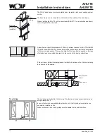
Flexible connections
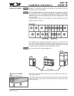
Remove the transportation locking devices.
During installation ensure that the connecting flanges are no more than 100 mm apart
to ensure that the flexible connections have their full range of movement.
It may be necessary to fully insulate the flexible connections on site against
acoustic emissions and condensation.
Ensure that the fan shaft is horizontal in its bearings. If the shaft is not perfectly horizontal
the ball bearing will suffer damage and service life will be substantially reduced.
Remove the transportation locking devices from fans mounted on spring-loaded vibration
dampers.
Note
Fan section
Transportation
locking devices
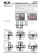
The heat exchangers (cooling coil, heating coil) operate on the countercurrent principle.
This means that the heat transfer medium or refrigerant moves in the opposite direction
to the air flow. Consequently, the flow connection for the medium is always on the air
discharge side of the heat exchanger.
Connect the heat exchangers so that no mechanical stresses and strains are transmitted
from the pipework to the heat exchangers.
It is also important to ensure that the transmission of vibrations and longitudinal expansion
and contraction between the air-handling unit and the pipework is effectively prevented.
Ensure that the connecting lines never obstruct access to the other parts of the unit
(fan, filter, scrubber, etc.).
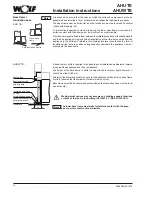
For the heat exchanger (with flange) it is recommended to use bends to make the
connections. This configuration will ensure that the heat exchanger and the mist eliminator
can be extracted to one side for subsequent cleaning.
Always install steam registers so that the steam inlet is always at the top (large diameter
connector) and the condensate drain is always at the bottom.
When connecting the flow and return lines, always use a wrench of correct size to
counterhold the threaded connectors of the heat exchanger. Otherwise the mechanical
force could separate the header from the heat exchanger. Damage of this nature would
effectively ruin the heat exchanger.
It is important to ensure that facilities for venting and draining are installed on site.
Always connect a siphon to the condensate drain connector of the cooling coil drip tray
(see "Siphon").
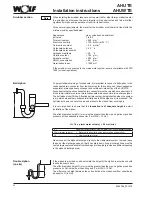
AHUW TE:
If the heat exchanger connections are on the inside, run the pipework
through the empty section provided for the purpose downstream of the heat
exchanger. Make adequate provision for venting.
Make suitable apertures through the removable base to accommodate the pipes.
Seal these apertures by suitable means after insulating the pipework.
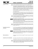
The weatherproof projection is not thermally insulated.
Consequently, the pipes
and valves must be adequately insulated and, if necessary, heated on site.
If an inverter is used for operation it is advisable to provide external ventilation
in summer to prevent overheating (max. permissible temperature 45 °C).
Provide suitable apertures through the removable base of the projection
to accommodate the pipes.
Note
Note
Heat exchanger
Removable heater exchanger
Flange
Removable mist eliminator
Empty section
Flow
Flow
Return
Return
Direction of air flow Direction of air flow
+


