20
3064058_201610
AHU TE
AHUW TE
Installation instructions
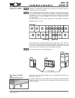
When installing the scrubber take care not to permit dirt or other foreign matter to enter
the scrubber, as otherwise the pump impeller will be obstructed and this will either
significantly impair pump operation or result in its destruction.
Given normal requirements, the water for the scrubber must comply at least with the
minimum quality specified below:
Appearance
clear, colourless, no sediment
pH value
7 to 8.5
Total salt content
< 800 g/m
3
Electr. conductivity
< 100 mS/m (at 20 °C)
Calcium ion content
> 0.5 mol/m
3
Carbonate hardness
< 4.0 °d
Carbonate hardness with
hardness stabilizers
< 20 °d
Chloride content
< 180 g/m
3
Sulphate content
< 290 g/m
3
KMnO
4
consumption
< 50 g/m
3
Germination index
< 1000 ml-1
If the scrubber is connected to the mains water system, ensure compliance with DIN
1988 [or local regulations].
Note
Scrubber section
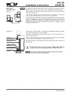
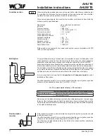
If the siphon is provided on site, calculate the height of the siphon in accordance with
the sketch shown here.
The effective siphon height H (mm) must be greater than the max. negative or positive
pressure (in Pa) inside the air-handling unit (1 mm WS = 10 Pa).
The difference in height between the unit outlet and the siphon overflow should also
be equal to H (in mm).
Double siphon
(on site)
Ball siphon
h
Never connect the siphon discharge directly to the wastewater system. Instead, leave
the end of the discharge open so that it can drain freely. Long discharge lines must be
vented to prevent condensate from backing up in the pipe (provide an additional opening
in the siphon discharge pipe).
To permit reliable draining of condensate, it is important to connect a ball siphon to the
condensate drain connector from the drain tray for the cooling coil / direct-expansion
evaporator, plate-type heat exchanger and outside air intake tray of the AHUW TE.
Also observe that each condensate drain connector must have a siphon connected to it.
It is not permissible to run two or more condensate drain connectors into a shared siphon.
The ball siphon is self-filling. A floating ball prevents air being inducted when the system
is dry, which means that condensate initially has to fill the siphon as it is produced. The
ball also acts as a non-return valve and prevents the siphon from sucking dry.
It is very important to ensure that the
foundation is of adequate height
to permit
installation of the siphon.
The effective siphon height H (mm) must be greater than the max. negative or positive
pressure at the condensate connector (1 mm WS = 10 Pa).
H = 1.5 x p (mm water column) + 50 mm (min.)
p =
Negative or positive pressure in mm of water column as per appliance design
50 mm (water column)
= Reserve (to allow for design inaccuracies, evaporation)
1.5
= Additional safety factor

